

MAINTENANCE
INSPECTION
B E F ORE INSPECTION OR ANY MAINTE
NANCE W ORK IS D ONE, BE SURE T HAT T HE
BREAKER IS IN T HE OPEN P OSITION.
ALL
E LECTRICAL P OWER, B OT H PRIMARY A ND
C ONTROL S OURCES, S HOULD A LS O BE DIS
C ONNECTED.
Periodic inspection of the circuit breaker
is recommended at least once a year.
More
frequent inspections are recommended, if severe
load conditions, dust, moisture, or other un
favorable conditions exist.
If
the breaker remains open or closed for
a long period of time, it is recommended that
arrangements be made to open and close it several
times in succession, preferably under load.
At all times it is important not to permit pencil
lines, paint, oil or other foreign materials to re
m ain on the insulating surfaces of the breaker
as they may cause low resistance between points
of different potential and result in eventual elec
trical breakdown.
Always inspect the breaker after a short
circuit current has been interrupted.
At the time of periodic inspection, the follow
ing checks should be made after the breaker has
been de -energized.
1 . Manuall y operate the breaker several times
checking for obstructions or excessive friction.
2 . Electrically operate the breaker several times
(if breaker has electrical control) to ascertain
whether the electrical attachments are func
tioning properly.
3 . Remove and inspect the arc quencher. Break
age of parts or extensive burning will indicate
ne ed for replac ement.
4.
Check contact condition and wip e
5 . Check latch engagement.
6. Check operation of tripping devices, including
overcurrent trip devices, making sure all
have positive tripping action.
(Discernible
movement in tripping direction beyond point
of tripping. )
(For detailed information o n breaker features
listed, refer to appropriate sections of these
instructions.)
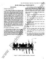
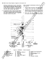
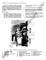
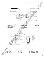
SEPARATION OF FRONT AND BACK FRAMES
Figure 3
Many maintenance operations will either re
quire or be greatly facilitated by separating the
front frame and mechanism of the breaker from
the back frame or base, which consists of the
current carr ying parts of the breaker and their
supporting struc ture.
The p rocedure for this
operation is as follows :
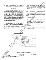
1 . Remove the arc quenchers (see section on
"Arc Quenchers ").
2. Disconnect the two insulated connecting links
(6), between the mechanism and the crossbar
( 10), by removing the tie bolt
(7),
and slipping
the ends of the links off the ends of the should
ered pin, {5) Figure 5 in the mechanism.
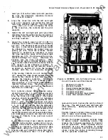
3 .
If
the breaker is a drawout type, with secondary
disconnects, Figure 2, remove the secondary
disconnect supporting bracket from the breaker
back frame. Also remove any wiring bundle
retainers that may be attached to the back
frame.
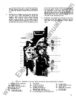
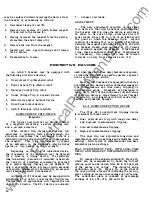
4.
Remove one elastic stop nut from each of
two s tuds (3), which tie the upper ends of the
mechanism frame to the back frame of the
breaker.
5. Remove the two elastic stop nuts {9/1 6 " Hex.)
which fasten the wrap around portion of the
front frame to the back frame. One of these
is located on each side of the breaker, about
2/3 of the distance down from the top edge
of the back frame.
On drawout breakers for AKD Equipment, the
bottom plate must be removed by first remov
ing two #8-3 6 screws located at the front of the
bottom plate and then freeing the plate from the
slots located in the bottom of the back frame.
6 . The two frames are now disconnected. How
ever, care should be exercised in separating
them to avoid dam age to the trip shaft arms
and paddl es.
While the back frame i s held
steady, lift the front frame and mechanism
up and out so that the trip paddles on the
trip shaft clear the trip arms of the overload
trip devices .
Reassembly of the two breaker halves is
accomplished b y following the procedure out
lined in reverse order.
LUBRICATION
In general,. the circuit breaker requires very
little lubrication.
Bearing points and sliding
surfaces should be lubricated very lightly at the
regular inspection periods with a thin film of
extreme temperature, high pressure, light grease,
similar to
G.
E . Spect. No. D50H1 5 or RPM No. 5.
Hardened grease and dirt should be removed from
latch and bearing surfaces by the use of a s afe
cleaning solvent such as kerosene. Latch surfaces
should be left clean and dry and not be lubricated.
5
www
. ElectricalPartManuals
. com


