
Power Circuit Breakers Types AK-2-15 and AK-2/3-25 GEI-50299
BASIC BREAKER COMPONENTS
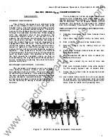
DISCONNECTS
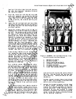
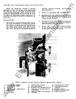
PRIMARY DISCONNECTS
The
disconnects are attached to the
ends of
breaker studs on the rear side of the
breaker base. Each disconnect assembly consists
of two pair of opposed contact fingers. These are
secured to the b:reake:r; stud by a bolt which passes
through the assembly and the stud. When engaged
with the stationary stud of the enclosure, the
disconnect fingers exert a set amount of force
against the stationary stud through the action of
the compression springs. Retainers and spacers
hold the contact fingers in correct alignment for
engagement with the stud. The amount of force
which the fingers exert against the stud is deter
mined by degree to which the springs are com
pressed by the bolt and nut which hold the assembly
together.
This pressure is factory set between
60
and 70 pounds.
If,
for any reason, the disconnects
must be taken apart, the position of the nut on
the bolt should be carefully noted, so that in
reasseml>lying, the original amount of compression
can be restored by replacing the nut at its former
position on the bolt.
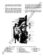
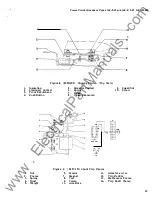
SECONDARY DISCONNECT,
FIGURE 2 .
The secondary disconnects serve as connec
tions between breaker control circuit elements
and external control circuits . They are used only
on drawout type breakers. A terminal board serves
the same purpose on stationary mounted and general
purpose enclosure mounted breakers . The second
ary disconnects allow removal of the breaker with
out the necessity of having to detach external con
nections.
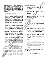
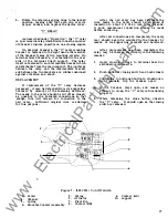
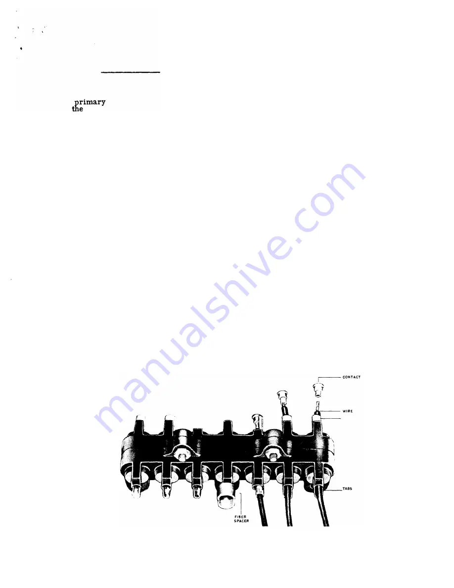
The movable part of the secondary disconnect
consists of an insulating body which holds a con
ducting spring loaded plunger to which a flexible
lead is attached. As the breaker moves into its
enclosure, the plunger is depressed by sliding
onto the stationary disconnects of the enclosure.
REPLACEMENT OF MOVABLE SECONDARY DIS
CONNECTS
1.
Unfasten disconnect body from breaker back
frame.
2 . Open tabs which hold wires on inner side.
3 . Pull contact tip loose from hollow tube.
4.
Remove contact tip by cutting wire at its
base.
5 .
Push wire through hollow tube of new dis
connect assembly.
6.
Strip insulation off end of wire to about
1/4
of an inch from end.
7.
Place new contact tip on end of wire and
crimp.
8.
Pull wire through hollow tube until contact
tip fits snugly against end of hollow tube.
9.
Crimp tab on other side of assembly to hold
wire in place.
10.
Any hollow tubes which are not used should
be pushed into the disconnect body and held
in that position by placing fibre spacers over
inner ends of tubes and spreading tabs.
TIP
HOLLOW
TUBE
Figure
2 .
(8017973)
Movable Secondary Disconnects
7
www
. ElectricalPartManuals
. com


