

1 1.
When all wires have been connected, refasten
the body of the assembly to the breaker back
frame.
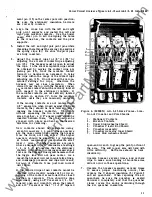
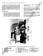
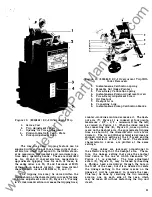
ARC QUENCHER
The arc quencher is an integral riveted as
sembly composed of two ceramic side plates, a
series of steel plates, and a muffler. The assembly
is covered by a wrap around of insulating material
which inhibits any sidewise emission of gases. The
steel plates are held in position and supported by
the ceramic sides which are grooved vertically
to provide recesses for the vertical edges of the
steel plates. The bottom edges of the latter form
an inverted
"V"
along the path
of
the arc that
may be drawn between the breaker contacts during
interruption. The steel plates have the effect of
breaking up the arc, and cooling it and the gases
that result from interruption. The entire assembly
provides a "chimney" effect which directs the hot,
ionized gases upwards through the steel plates and
mufflers and allows their safe and controlled
escape at a cooler temperature.
The muffler at the top of the assembly is a
serpentine shaped strip of perforated, copper plated
steel.
It
is important that the perforations of the
muffler be kept open, since their closure could
tend to prevent the escape of the gases along the
desired path. At the regular maintenance inspec
tion, it would be well to check their condition and
open any of the perforations that appear to be
clogged.
If
any very extensive burning or corrosion
is noted in the arc quencher, it should be replaced.
Replacement is also indicated if any breaks or
cracks are noted in the ceramic material.
REPLACEMENT
Removal of the arc quencher is simply a matter
of lifting the assembly up and out, after the steel
retainer across the front of the arc quenchers has
been removed. The upper edge of the steel arc
runner, fastened to the back plate of the breaker,
fits into a recess in the back portion of the arc
quencher which locates it in its proper position
upon replacement. Make sure the steel retainer
is replaced and fastened firmly to its mounting
studs after the arc quenchers have been replaced.
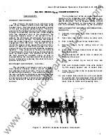
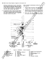
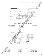
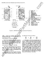
BREAKER CONTACT STRUCTURE
The copper current carrying parts of the
breaker are all mounted on a common base of
insulating material made of polyester glass mat.
The copper of each pole consist of an upper stud
and pivot, stationary contacts, two movable contact
arms, a movable contact pivot, and the lower stud.
The upper stud branches into two pivot surfaces
on its inner end on the forward or front side of
the breaker base.
Each of these convex pivot
8
surfaces mates with the concave pivot surface on
the rear side of the stationary contacts. Each
of
the stationary contacts pivot in a horizontal plane
approximately at their mid-points. The end of the
contact opposite to the contact tip end
is
formed
into the shape of a small hook. A tension spring
engages this hook and provides the necessary
contact pressure at the pivot and also at the point
of contact with the movable contact arm. When the
breaker contacts open, a projection on the contact
tip end of the stationary contact bears against a
stop pin restricting the movement of the stationary
contact. This arrangement results in a continual
high force existing between the mating pivot
surfaces.
The movable contact arms pivot in
J.
vertical
plane, each making contact with a pair of stationary
contacts, and thus providing four low resistant
parallel paths of current for each breaker pole.
The movable contacts rotate
about
a burnished,
silver plated, copper pin which, in turn,
is
held
by a pivot support. Each side of the pivot support
bears against the lower, outer surface of the contact
arm and supplies a second low resistance path
through the pivot. A "U" shaped spring clip made
of silver plated conducting material provides an
additional current path and protects the other con
tact surfaces of the pivot against pitting when in
motion.
It
also contributes to the force tending to
increase the contact pressure between the lower
ends of the movable contacts and the pivot support.
The movable contact pivot support is mounted
securely to the breaker base.
If,
as is normally
the case, the pole is equipped with an overcurrent
trip device, one of the terminals of the series coil
of the trip unit is fastened to the lower end of
the pivot support.
The other terminal of the
coil fastens to the lower stud.
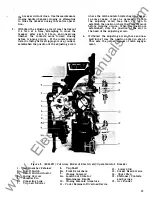
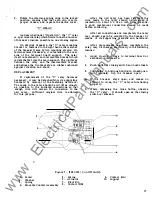
CONTACT ADJUSTMENTS
The only adjustment to be made on the breaker
contacts is that of contact wipe. This may be
described as the distance the movable and station
ary move while they are touching one another in
the process of breaker closing. The amount of
contact wipe can be measured by comparing the
position of the front surface of the stationary
contact when the breaker is open to its position
when the breaker is closed, in reference to some
absolutely stationary part of the breaker. The
most convenient stationary part of the breaker to
use as a reference point is the steel arc runner
above and behind the stationary contacts.
The amount of wipe the contacts should have
is nominally
1/8
of an inch.
A plus or minus
tolerance of
1/32
of an inch is allowed.
The means of adjusting contact wipe is pro
vided by an eccentric pin which passes through
the center of the movable contact assembly. Each
end of this pin has a free, projecting, hexagon
•
www
. ElectricalPartManuals
. com


