
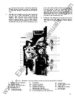

•
shaped section which is easily accessible to a
small, open end, 1/4 inch wrench. Two cantilever
springs, which bear on each end against a portion
of the hexagon section of the pin, lock the ad
justing pin in place and provide index stops for
the process of adjustment. The right hand hexagon
shaped end of the pin is numbered from 1 to 6,
which provides a reference for making wipe
adjustments.
When contacts are to be adjusted, the recom
mended procedure is as follows:
1.
With the breaker in the open position and using
the numbers on the right end of each adjusting
pin as a reference, set each pin in the same
position.
In
many cases
�
the number 3 is a
good beginning point. The proper view of the
number on the adjusting pin is obtained by
viewing the breaker from the front and the
adjusting pin from approximately a 15 degree
angle with respect to the movable contacts.
Note that the numbers on the pin are not in
numerical sequence as the pin
is
rotated.
2 .
By measurement, establish the position of the
front surfaces of the stationary contacts with
reference to the steel arc runners above and
behind the contacts.
3. Close the breaker, and establish the amount
of wipe by again measuring as in step two,
and comparing the measurements with those
taken with the breaker open.
4. If any set of contacts lead or lag the others,
open the breaker and advance or retard the
pin to the next higher or lower
number. Moving the adjusting pin to a higher
number will increase the contact wipe and
moving to a lower number will decrease the
contact wipe.
NOTE: No attempt should be made to move
the adjusting pin when the breaker is closed.
Besides being more difficult, the additional
force required to move the pin will tend to
round off the flats of the hex section of the pin.
5. When all the contacts have the recommended
wipe of 3/32 to 5/32 of an inch, the contact
adjustments are complete.
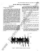
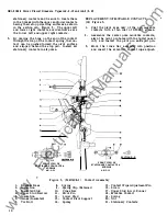
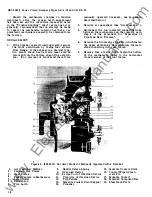
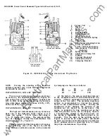
CONTACT REPLACEMENT
Figure 3
The normal situation that will exist in the
matter of contact replacement will call for re
placement of all the movable and stationary con
tacts at the same time. This will be the case
where long use of the breaker in service has
resulted in extensive wear or erosion of the
silver alloy contact tips.
A commonly used
" rule of thumb" is that contact replacement is
indicated if less than one-half of the original
thickness (1/8 of an inch) of the contact tip
material remains.
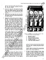
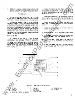
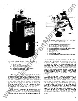
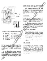
GENERAL PREPARATION
1.
Remove arc quencher retainer (1 )
,
Fig\lre 5
bY. loosening the two captured nuts with a
7716" wrench.
2 .
Lift off the three arc quenchers.
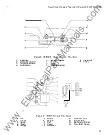
3. Remove the U shaped insulation (5) Figure 3
from each pole by 'lifting it and disengaging
the rivet heads thru the keyholed slots in the
insulation.
4.
As an aid to future reassembly of the movable
contacts, note the position of all stationary
insulation barriers with respect to barriers
mounted on the cross bar.
REMOVAL OF MOVABLE CONTAC TS
( 18) Figure 3.
1. Screw the threaded end of the steel rod
lightly into pivot pin (11) on the right pole.
2. With a pair of long nosed pliers, unhook
safety pin type spring clip (9) and extract
pin (11) and remove spring clip (9).
3 . Grasp movable contact assembly and remove
it from its seat on the cross bar.
4.
Repeat procedure 1,
2,
and
3
above on the
left pole.
5. Move the cross bar downward to disengage
it
from the contact wipe adjusting pin (15)
on the center pole, then move the cross bar
toward the front of the breaker.
6.
Remove the split pin retaining the center
pole pivot pin.
7.
Remove the pivot pin and movable contact
assembly.
REMOVAL OF STATIONARY CONTACTS
(2 1) Figure 3 .
1. Slip the blade of a heavy screw driver between
the two upper contacts and force the contacts
toward their pivot point sufficiently far to
disengage the contact stop surface from the pin.
2 .
The contact can then b e removed by disengaging
the end of the contact from its spring.
3.
The two lower contacts can be similarily
removed.
REPLACE MENT OF STATIONARY CONTACTS
(2 1) Figure
3 .
1. Coat the contact pivot area only of each of
the four contacts with a thin coat of D50H47
grease. Use only D50H47 grease.
2 .
Note the difference between the two types of
9
www
. ElectricalPartManuals
. com


