CLOSING SOLENOID
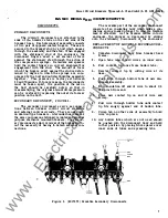
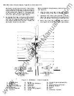
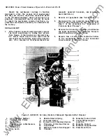
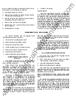
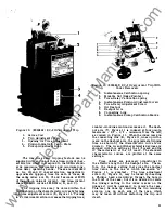
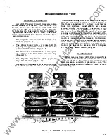
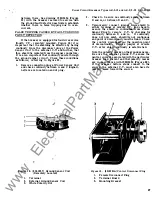
The closing solenoid consists of a magnet,
armature and coil.
This assembly is located
directly beneath the breaker mechanism to which
it is connected by a link which ties the upper end
of the armature
to
the spring carrier of the
mechanism. (See Figure 5.)
When voltage is
to the coil, the
magnetic force
pulls the armature up
into the coil and magnet assembly.
This, in
turn, rotates the spring carrier about its pivot,
extending the mechanism spring and causing its
line of action to move "over center", resulting
in a closing operation.
REPLACEMENT
The only replacement operation that might
conceivably be required on this assembly is
that
of
the solenoid
coil.
To replace this, proceed
as follows :
1.
Remove escutcheon by unfastening four flat
head screws in flange.
2.
Remove closing switch. (See "Closing switch ".
)
3.
C ut off or disconnect the coil leads.
4.
Remove four screws which fasten lower s ection
of magnet to upper section.
5.
Allow lower s ection of magnet and coil to
need not be removed from the old bracket. This
can be taken off the breaker simply by removing
the two screws which fasten it to the breaker frame.
If
the breaker is a drawout type, the supporting
bracket of the
"Y"
relay may be temporarily
displaced to provide access to the screws.
Since the expendable parts of the
"X"
contactor
are the contacts and the coil, ease of replacement
of these parts has been designed into the relay.
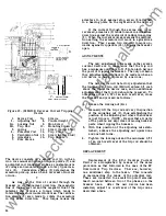
Methods of procedure are as follows:
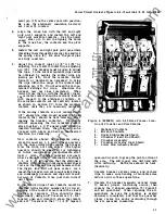
Contacts
1.
Remove relay cover.
2.
Remove terminal binding screw of stationary
contact to be replaced.
3.
Lightly pinch with pliers (pointed end) the
split section of the contact which enters the
hole in the compound body of the device and
lift out the stationary contact.
4.
5.
6.
With
the fingers, pull forward on the spring
guide of the movable contact, compressing
the contact spring as far as possible.
With the spring thus held, grip the end of the
contact strip with pointed pliers, turn
it
through
90
degrees on its long axis,
an d
withdraw it.
Replace new contacts by
reversing the pro
cedure.
slide
downwar d until clear of armature.
Coil
6.
Reassemble with new coil by reversing order
of procedure.
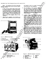
" X "
C ONTACTOR
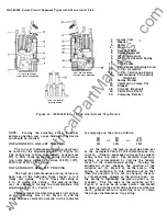
The " X" contactor is a heavy- duty relay which
performs the function of closing the circuit of the
breaker solenoid during electrical operations.
Three of the four sets of contact of the device are
arrange d in series to m inimize the duty require d of
any one contact. As e xplained un der "Operation",
the fourth contact is use d to "seal-in" the
"X"
coil.
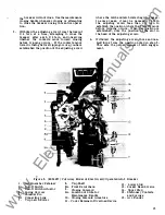
The
"X"
contactor is located on the right
beneath the horizontal front frame member. It
is mounte d on three studs which fasten it to a
mounting bracket which is s uspended from the
frame.
Rubber bushings on the mo unting studs
provide anti-vibration and anti-shock protection
for the relay.
The relay contacts and their
terminals are covered by a mol de d piece of
ins ulation which fits over spring clips that hold
the cover in place.
REP LACE MENT
Removal of the complete device is accomp
lishe d by removing the cover, disconnecting the
leads from the terminals, and removing the nuts
from the three mounting studs .
If
the replacement
unit includes the mounting bracket, the relay
16
1.
Remove relay cover.
2.
Turn the two retaining spring clips on the ends
of the device through
90
degrees about their
p ivots.
3.
P ull out the two halves of the body of the devic e
which carry the stationary contacts . When
these are clear of the frame, the armature
and movable contact assembly will move aside ,
e xposing the coil.
4.
Remove the termin al screws of the coil and
p ull it free of its retaining spring clips.
5.
Place new coil on pole piece inside of the
spring clips and fasten terminals to leads.
6.
Just start the replacement of one of the
compound blocks which hold the stationary
contacts into its groove in the frame.
7.
Position the armature and movable contact
assembly to allow the entrance of the second
stationary contact block.
8.
When these parts are all properly aligned,
with the stationary contacts un der the movable
contacts, push them into their g uiding grooves
in the frame
until
they bottom.
•
www
. ElectricalPartManuals
. com

