1 3.2 SERIES OVERCURRENT TRIPPING
DEVICE Ec-1
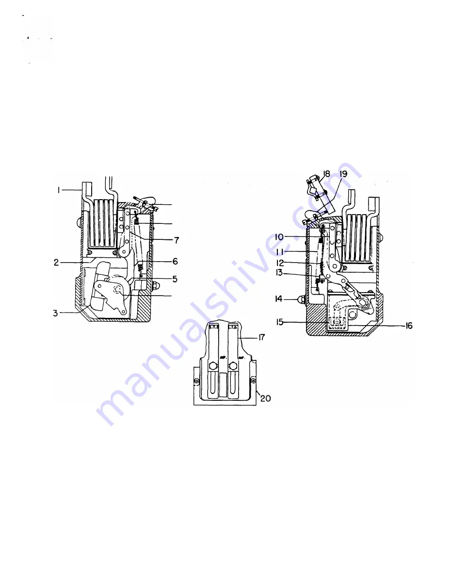
Each series overcurrent tripping
device
is enclosed in a
molded case and mounted by screws and a bracket to the lower
part
of
the pole unit base.
Refer to Fig. 1 01 for the discussions below.
1 3.2.1
SHORT TIME-DELAY TRIPPING
The armature (7) is restrained by calibrating spring (8). After
the magnetic force produced by
an
overcurrent condition over-
9
8
4
Left Side VIew Showing
Short Time Delay Mechanism
comes this restraining force, the armature movement is further
retarded by an escapement mechanism which produces an in
verse time delay characteristic.
The
mechanism is shown on
Fig. 1 01 .
1 3.2.2
LONG TIME-DELAY TR
I
P
PIN
G
The
armature (1 0) is restrained by the calibration spring (1 1 ).
After the magnetic force produced by an overcurrent condition
overcomes this restraining force, the armature movement is fur
ther retarded by the flow of silicone oil in a dashpot, which pro
duces
an
inverse time delay characteristic. The mechanism is
shown on Fig. 101.
Right Side VIew Showing
Long Time Delay Mechanism
Front VIew Showing
Mounting Bracket
1
.
Series
Coil
8. S.T.D. Calibration Spring
15. Plunger
2. Magnet
9. Trip Paddle Adjusting Screw
1 6. Cylinder
3. Pallet
10. L.T.D. Armature
1 7. Calibration Plate
4.
Pinion
1 1 .
L
T.D. or Low-set lnst. Calibration Spring
18. Trip Paddle
5. Escape
Wheel
12. lnst. Trip Spring (High
Set)
19. Trip Arm
6. Driving Segment
1 3. Spring Holder
20.
Clamping Bracket
7. S.T.D. Armature
14. C&libration Clamp
Nut
RG.
1 01 SERIES OVERCURRENT TRIPPING DEVICE EC-1
73
www
. ElectricalPartManuals
. com


