8.6 CONTACT REPLACEMENT
AKA 30/30H & AKRU 30
Refer to Stationary Contact Identification , Section 8.5
before replacing any stationary contacts.
The stationary contacts are held in place by the contact
springs which pivot the contacts agai nst the contact stop,
refer to Fig. 45. To replace contacts:
1 . Remove the arc runner. It is secured by two screws
into the base and one screw into the contact stop.
2. Release each contact spring by holding the contact,
extending the spring, and removing it from the contact. The
end pieces on each spring have a small hole for inserting a
spring puller. A suitable puller can be fashioned by forming
a hook on the end of a length of .062" diameter steel wire.
A spring puller is available for this use and may be
ordered under Cat. No. 286A81 68G1 .
3 . Clean off the existing lubrication on the stud's pivot
area. Replace with a small amount of D50H D38 (MO B I L
2 8 ) before installing new contacts.
4. Torque the upper arc runner mounting screws to 45
±
5 in-lbs. Torque the lower screw to 35-40 i n-lbs.
The movable contacts are removed as foll ows, referring
to Fig. 46.
1 . Using a right angle tru-arc pliers, remove the tru-arc
retai ner on the coupling pin. Drift out the coupling pin.
2. Remove the pivot piA hardware and spring from one
side of the pivot pin. Careful ly remove the pivot pin.
3. Slip out the contact arm.
4. Place a thin film of D50H D38 lubrication on the pivot
surfaces of the new arm. Clean any existi ng lubrication
from the pivot pin and place a smal l amount of D50HD38
on it.
5. Install the new arm, insert the pivot pin, and replace
the pivot
and hardware. Tighten the pivot pin hard
ware to 90 ±
i n-lbs.
6. I nstall the coupling pin and tru-arc retainer.
7. Make the contact adjustment as per section #8.2.
8.7 CONTACT REPLACEMENT-
AKA 50/SOH, AKRU 50 & AKRT 50/SOH
Refer to Stationary Contact Identification, Section 8.5,
before replacing any stationary contacts.
The stationary intermediate and main contacts are
replaced j ust l i ke the stationary contacts on the 800
ampere breakers. Refer to steps 2 & 3 in Section 8.6
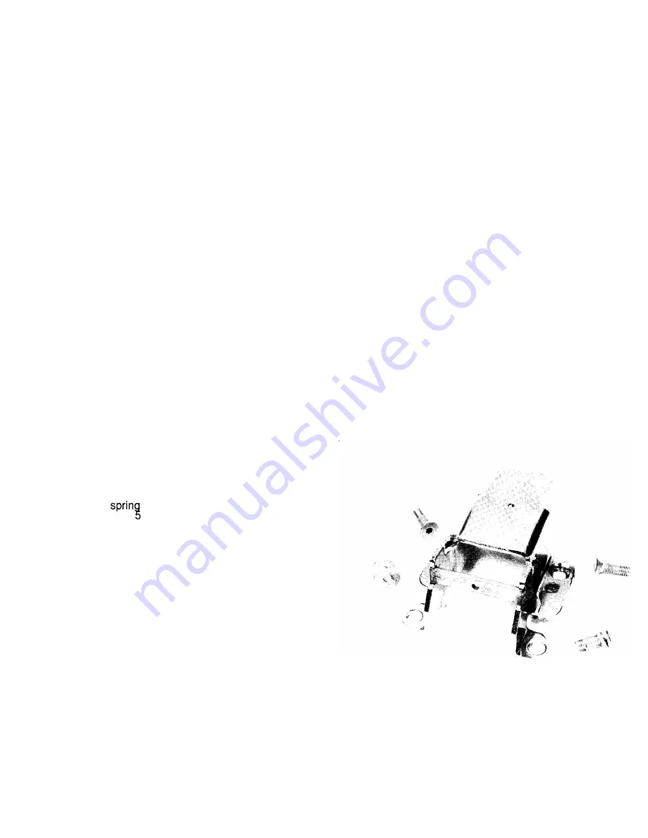
Referring to Fig. SOA, SOB & SOC, the stationary arcing
contacts are replaced as follows.
1 . Remove the arc runner and the flat insulation
assembled underneath the arc runner. It is secured with
four screws. When removing the lower screws, use care
not to damage or misplace the insulating washer found
under each of these screws, see Fig. SOA.
2. Remove the Arcing contact pivot. Clean off the exist
ing lubrication found on the pivot area. Replace with
D50HD38 (MOBIL 28) , see Fig. 50B.
3. Remove the insulating spacers, contact pin and arc
ing contacts, see Fig. 50C.
4. Reassemble the reverse of above. Make sure that the
insulating spacers and insulating washers are properly in
stalled. Torque the arc runner hardware to 45
±
5 i n-lbs.
The movable contacts are removed in a similar manner
as the 800 ampere breaker movable contacts. Refer to
Section 8.6. When removing the pivot pin from a 2000
ampere (AKRT 50/SOH) contact assembly, the pivot pin
from the opposite contact assembly must be sl ightly
removed. This provides enough c learance to completely
remove the pivot pin.
I
INSULATING
WASHER
ARC R U N N E R
FIG. SOD -
INSULATING
l""
STATIONARY CONTACT -1 600/2000 AMP
REPLACEMENT CONTACT STRUCTURE
39
www
. ElectricalPartManuals
. com


