background image

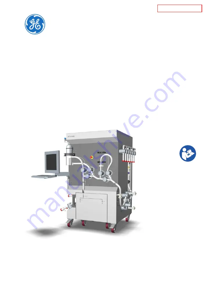
ÄKTA™ ready XL

Operating Instructions

Original instructions

gelifesciences.com

*** TeDIS Valid on Date Printed        Printed on: 15-09-2023 11:27:35 ***

185018004599

Summary of Contents for AKTA ready XL

Page 1: ...KTA ready XL Operating Instructions Original instructions gelifesciences com TeDIS Valid on Date Printed Printed on 15 09 2023 11 27 35 185018004599...

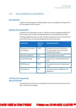
Page 2: ...arts and components 65 3 5 3 Gradient section and components 71 3 6 Processcontrolsoftware 72 4 Installation 76 4 1 Siterequirements 77 4 2 Transportandmovingofthesystem 78 4 3 Setup 86 4 3 1 Assembly...

Page 3: ...ontact information 158 9 5 2 European Union and European Economic Area 159 9 5 3 Eurasian Economic Union 160 9 5 4 Regulations for USA 162 9 5 5 Regulatory statements 163 9 5 6 Declaration of Hazardou...

Page 4: ...rmation intendeduseof KTAreadyXL andlistsofassociateddocu mentation In this chapter Section Seepage 1 1 Aboutthismanual 5 1 2 Importantuserinformation 6 1 3 Associateddocumentation 9 1 4 Abbreviations...

Page 5: ...UNICORN softwareinstructionsareprovidedasexamples Forothercontrol softwareinstructions refertothesoftwaredocumentation Detailedinformationregardingcolumns resinandbuffertanksisnotcovered Illustrations...

Page 6: ...softwareorothercontrolsoftwares suchas DeltaV Thesystemdesignisbasedonprovenliquidchromatographytechniques suchasion exchange affinitychromatography andhydrophobicinteraction KTAreadyXL isbiocompatib...

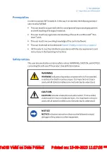
Page 7: ...ces Thisuserdocumentationcontainssafetynotices WARNING CAUTION andNOTICE concerningthesafeuseoftheproduct Seedefinitionsbelow WARNING WARNINGindicatesahazardoussituationwhich ifnotavoided couldresulti...

Page 8: ...or trouble free and optimal use of the product Tip A tip contains useful information that can improve or optimize your proce dures 1 Introduction 1 2 Importantuserinformation 8 KTAreadyXLOperatingInst...

Page 9: ...vi ation Purpose Contents PipingandInstrumenta tionDiagram P ID Schematicoverviewoftheprocess flow componentsandinstruments andthecontrolsystem Generalspecification GS Technicaldataforthesystem Assemb...

Page 10: ...ual 28925644 ReadyToProcess columns Datafile 28915987 Process chromatography A guide to op timization scale up and validation Handbook 18112156 Efficiency test of ReadyToProcess col umns Application n...

Page 11: ...m Definition CU Controlunit PBS Phosphate bufferedsaline PTFE Polytetrafluoroethylene TC Hygienictubingconnection UPS Uninterruptiblepowersupply XV Pneumaticallyactuatedvalve automaticvalve 1 Introduc...

Page 12: ...clinginformation In this chapter Section Seepage 2 1 Safetyprecautions 13 2 2 Labels 21 2 3 Emergencyprocedures 24 Important WARNING Beforeinstalling operatingormaintainingtheproduct all usersmustread...

Page 13: ...ssmentforanyrisksdueto theprocessorprocessenvironment Evaluatetheeffectstheuse oftheproductandtheoperationalprocessesmayhaveonthe classificationofthehazardousarea Theprocessmightcausethe areatoincreas...

Page 14: ...KOUT TAG OUT LOTO lockout tagout WARNING Onlyauthorizedpersonnelmayopentheelectricalcabinetdoors Thereishighvoltageinsidetheelectricalcabinetthatcancause humaninjuryordeath WARNING Emergencystop Press...

Page 15: ...RNING PersonalProtectiveEquipment PPE Wheneverpacking un packing transportingormovingthesystem wearprotectivefoot wear preferablywithsteeltoecaps Installing and moving WARNING Theproductmustbeinstalle...

Page 16: ...ystem CAUTION Beforemoving KTAreadyXL makesurethat 1 Thepowersupplytothesystemisswitchedoff 2 Allpowercordstothesystemaredisconnected 3 Allairsupplylinestothesystemaredisconnected 4 Allprocesslinestot...

Page 17: ...switchmustalways beeasytoaccess WARNING NationalCodesandstandards NEC VDE BSI IEC ULetc andlo calcodesoutlineprovisionsforsafelyinstallingelectricalequip ment Installationmustcomplywithspecificationsr...

Page 18: ...rainageorotheractivitiesthatmayinvolvesplashing WARNING Useaharmlessfluidinthebeginningoftheprocess Thiswill makeitpossibletodetectleakagewithminimizedconsequences andtheriskforpotentialleakageofhazar...

Page 19: ...eoperatormustalwaysmakesurethatnooneispresent andexposedwhenthesystemisstartedandthatnooneenters theriskareaaroundthesystemduringoperation CAUTION Shutdowndoesnotautomaticallyresultindepressurizingoft...

Page 20: ...misclearlytaggedastakenoutofoperation allprocesswettedareasareremovedorcleanedanddecon taminated WARNING Onlyauthorizedpersonnelmayperformservice installation and maintenanceofcomponentsinsidetheelect...

Page 21: ...ationcodeofthemanufacturingfacility Shortcircuitcurrentrat ing Themaximumcurrentthesystemcanwithstand TotalFLA Thefullloadampere LargestmotorFLA Thelargestmotorinstalledonthesystem Protectionclass The...

Page 22: ...ThesystemcomplieswithapplicableEuropeandi rectives Thissymbolindicatesthattheproductcontains hazardousmaterialsinexcessofthelimitsestab lishedbytheChinesestandardGB T 26572 Require ments of concentra...

Page 23: ...me type and rating of fuse Warning Highvoltageinsidethecabinet Author isedpersonelonly Forcontinuedprotectionagainstfirereplaceonly withsametypeandratingoffuse IMPORTANT Beforeservice maintenanceorret...

Page 24: ...icalcabinet WARNING Emergencystop PressingtheEMERGENCYSTOPdoesnotau tomaticallydepressurizetheflowpath WARNING Powerfailure Duringapowerfailure oriftheEMERGENCY STOPbuttonispressed thesystemmayremainp...

Page 25: ...thefollowing Pumpmotorsstopimmediately Thebuilt incomputerandothercomponentswillremainpowered Nodatawillbelost Thevalveswillshutdowninaspecificorder fordetailsseeValve shutdown order on page 26 2 Safe...

Page 26: ...139 Valve shutdown order WhentheEMERGENCYSTOPbuttonisusedtostopthesystem thevalveswill closeinthefollowingorder 1 Inletvalves 2 Airtrapvalves 3 Filtervalves 4 Columnvalves 5 Outletvalves Restart after...

Page 27: ...emergencyshutdown makesurealllinesandvesselsaredepressurizedbeforeopening Thesystempowerislostifthe Powerswitch ontheelectricalcabinetisturnedoff themainscableisdisconnected orifthepowersupplyfails Al...

Page 28: ...eturnswithinoneminuteafterthepowerfailure thecommunicationtothe serverandtheinterfacecontrolunitofthecontrolsoftwarewillautomaticallystart upagain Theselectedmethodthatwasrunningwhenthepowerwaslostwil...

Page 29: ...ollowinganemergency shutdownorpowerfailure contact GEHealthcare forfurtherad viceandassistance 2 Safety instructions 2 3 Emergencyprocedures KTAreadyXLOperatingInstructions29281616AE 29 TeDIS Valid on...

Page 30: ...iththesystem aredescribedinSection 3 5 Flow kits on page 62 In this chapter Section Seepage 3 1 Overview 31 3 2 Illustrations 33 3 3 Flowchart 43 3 4 Systemcomponents 47 3 5 Flowkits 62 3 6 Processcon...

Page 31: ...enticaldiaphragmpumps Thewagonisequippedwithfourcas tersmadeofpolyurethane Allofthecastersarelockable Technicalspecifications areprovidedintheBillofMaterialandinthemanufacturer suserdocumentation Onth...

Page 32: ...iononthecomputerandcomponentsintheelectricalcabinet Ifothercontrolsoftwarethan UNICORN isused nooperatorconsoleisfittedtothe systemframe Aninterfacecontrolunitofthecontrolsoftware forexamplePI 960 for...

Page 33: ...t and gradient section are described in Section 3 5 Flow kits on page 62 Part Function A KTAreadyXL system B KTAreadyXL flowkitandgradientsection orderedseparately 3 System description 3 2 Illustratio...

Page 34: ...ectionpointsforthesystem seeLo cation of connectors on page 42 3 Power switch Thesystemmainspowerswitch located ontheinletside leftside ofthesystem 4 Resetbutton TheResetbuttonmustbepressedafter thesy...

Page 35: ...rsensorAE 151communica tioncord 7 Inletvalves XV 011 to XV 014 Fourinletvalves locatedontheinletside leftside ofthesystemforpumpB 8 Inletvalves XV 001 to XV 006 Sixinletvalves locatedontheinletside le...

Page 36: ...unction 12 Levelsen sors fitting bracketand cablesfor connectors totheairtrap levelsensors LEL 166 and LEH 167 ThelevelsensorsLEL 166andLEH 167 areusedtomeasuretheliquidlevelinthe airtrap 13 Airtrapho...

Page 37: ...reprefitted 17 Sensorplug forpressure sensor PE 111 Sensorplugforthecommunicationcable forpressuresensorPE 111whichisprefit tedontheflowkit 18 Pumpwagon door Easyaccesstothepumpwagon 19 Sensorplug for...

Page 38: ...tisprefittedontheflowkit 22 Column valves XV 031 to XV 035 Afive valveassemblyforcolumnbypass inline upflow anddownflow 23 Sensorplug forpressure sensor PE 113 Pressuresensorplugforthecommunica tionca...

Page 39: ...E 121 TE 121 AcableforconnectiontopHmeter AE 121 TE 121thatisprefittedonthe flowkit 27 Cablefor connection toUVsensor AE 131 AfiberopticcableforconnectiontoUVme terAE 131thatisprefittedontheflowkit Ca...

Page 40: ...stem Thesystemisshownwithoutflowkit 30 29 28 Part Function 28 Inletforlowercoolingunits 29 Outletforuppercoolingunit 30 Systemelectricalcabinetdoor 3 System description 3 2 Illustrations 40 KTAreadyXL...

Page 41: ...36 35 33 37 34 35 32 Part Function 32 Pumpheaddriveunit 2pcs 33 Pressureplateforpumphead 2pcs 34 Pumpwagonhandlebar 35 Pumpwagonlock 36 Casterwheelwithwheelbrake 4pcs 37 Pumpmotor 2pcs withcovers 3 Sy...

Page 42: ...th UNICORN arelocatedonthefrontofthesystem 38 39 40 41 42 Part Functionaltagname Function 38 Pneumaticsupply Compressedairconnector 39 Profibus PROFIBUSconnector 40 Ethernet Ethernetnetworkconnector 4...

Page 43: ...owkitcomponentsandtubing wettedcompo nents Orangecolorillustratesgradientsectioncomponentsandtubing wettedcom ponents Redcolorillustratescustomersuppliedfilter optional andcolumn wettedcom ponents 3 S...

Page 44: ...XV 005 XV 006 BA6 BA5 BA4 BA3 BA2 BA1 M201 A P 201 B XV 012 XV 014 XV 011 XV 013 BB4 BB3 BB2 BB1 M201 B L L LEH 167 LEL 166 XV 023 W XV 021 XV 024 AT 221 XV 025 XV 026 XV 027 F1 F2 XV 022 CE 102 TE 10...

Page 45: ...TE 102 Conductivitysensor FE 141 Flowmetercell LEL 166 Airtraplowlevelmeter LEH 167 Airtraphighlevelmeter P 201 A Isocraticpumpmotor P 201 B Gradientpumpmotor PE 111toPE 113 Pressuresensors XV 001toX...

Page 46: ...Columntopoutletvalve XV 033 Columnbottominletvalve XV 034 Columnbottomoutletvalve XV 035 Columnbypassvalve XV 051toXV 056 Outletvalves 3 System description 3 3 Flowchart 46 KTAreadyXLOperatingInstruct...

Page 47: ...ittersandsensors 60 Introduction Thissectionprovidesdescriptionsof KTAreadyXL andanoverviewofallcompo nents includingthecontrolsystem Forfurtherdetailsandspecifications refertothedocumentationpackagep...

Page 48: ...nfacility Thestainlesssteeldesignsupportsprocesscomponentsandtheelectricalcabinetin oneunit Theelectricalcabinetservesasthecontainerfortheelectricalandpneu maticequipment Thesystemiseasytomoveandkeepc...

Page 49: ...trollinginterfacebetweenthecontrolsoftwareandthecom ponentsof KTAreadyXL Forsystemwith UNICORN controlsoftware thecontrolunitCU 960islocatedinside theelectricalcabinetandhascapabilitiestostorerealtime...

Page 50: ...lled computershutdownintheeventofapowerfailure Operator console only applicable to systems with UNICORN Thetouchscreenmonitorandkeyboardareergonomicallydesignedforusageina cleanproductionenvironment C...

Page 51: ...equippedwithtensionrollersanda drivebeltmotor Referthemanufacturer sproductdocumentationforfurtherde tails Thepumpmotorsareconnectedtothesystemandfittedtothepumpwagonunder thesystematdelivery Thepumpw...

Page 52: ...dtoPE 111toPE 113 Theoutput valuesofthetransmittersarehardwiredtothesafetymodule Ifanyofthemonitoredparametersreachesacriticallimit thesafetymoduleshuts downthepumpsindependentlyfromthesoftwarecontrol...

Page 53: ...itoringlimits Steadylight Acriticallimitisdetectedbythesafetymonitoring ortheEMERGEN CYSTOPbuttonhasbeenpushed Analarmisdisplayedinthe UNICORN controlsystem Flashinglight1Hz Thecauseofthealarmisaddres...

Page 54: ...must also be pressed after using the installation switch 3 System description 3 4 Systemcomponents 3 4 3 Systempumps 54 KTAreadyXLOperatingInstructions29281616AE TeDIS Valid on Date Printed Printed o...

Page 55: ...fromacciden tallyclosingduringflowkitinstallation Thelargevalvesarealsoequippedwithtwo typesofvalvesafetycovers Note To open or close safety locks the installation switch must be set to Flow kitinstal...

Page 56: ...ion of the pin to lock or unlock varies due to how the valves are fitted on the system The direction to lock the valve is indicated with an arrow and a lock symbol at each valve 2 Openthetwovalvesafet...

Page 57: ...Slidethevalvefingerguardtoopenthevalvetubingcompartment 3 System description 3 4 Systemcomponents 3 4 4 Valves KTAreadyXLOperatingInstructions29281616AE 57 TeDIS Valid on Date Printed Printed on 15 09...

Page 58: ...eright hand sideofthesystem Bypass XV 051to XV 056 Outletvalves locatedontheright hand sideofthesystem Closed RefertotheSoftwareDesignSpecificationformoreoptionsanddetails Air trap valves Theairtrapva...

Page 59: ...alves Bypass XV 026 Inline default XV 025 XV 027 Column valves Thecolumnvalvesetconsistoffivevalves Seethevalvemacrosforthecolumnin structionoptionsbelow Valvepositions Openvalves Bypass XV 035 UpFlow...

Page 60: ...lcabinet Flow transmitter KTAreadyXL isequippedwithamagneticflowtransmitterFT 141locatedoutside theelectricalcabinet Conductivity and temperature transmitter Twoconductivityandtemperaturetransmitters...

Page 61: ...on A B Thesensorassemblyconsistsofalowlevelsensor LEL 166 A andahighlevelsen sor LEH 167 B SeealsoCalibration of level sensors on page 144 3 System description 3 4 Systemcomponents 3 4 5 Transmittersa...

Page 62: ...mponents 71 Introduction Thischapterprovidesdescriptionsofthedisposableflowkitsandanoverviewofthe components Forfurtherdetailsandspecificationsrefertothedocumentationpackageprovided withthedelivery 3...

Page 63: ...Flow kit ordering information on page 152 Specificationsregardingtheflowkitsandsections includingmaterialsarefoundin theproductdocumentationprovidedwiththeflowkit Forchemicalresistanceta blesseeSecti...

Page 64: ...tedtoaperiodof14daysfromtheinitialwettingoftheflowkit After48 hoursofusageor14daysafterinitialwettingoftheflowkit thekitmustbediscar ded 3 System description 3 5 Flowkits 3 5 1 Flowkitdescription 64 K...

Page 65: ...ectingtothepumphead includingair sensorAE 151 2 Pumpchamber head Pumpchamberwithoneconnectorfortheinlet manifoldandoneoutletforconnectingtotheair traptubing 3 Airtrap filtertub ing Tubingwithoneconnec...

Page 66: ...13 14 15 16 17 18 Thefollowingtablegivesabriefdescriptionoftheflowkitcomponents Numbersin thetablerefertotheillustrationabove Note Several flow kit components are flow cells for sensors located on the...

Page 67: ...hepressurebe tweenthepumpandtheairtraporfil ter andispartofthehighpressure safetymonitoring 5 Airtrap AT 221 Airtrapallowsforremovalofairinbuf fersandsample Levelcontrolisper formedviacontrolsystemsof...

Page 68: ...corresponding tovalvesXV 051toXV 056 10 UVflowcell AE 131 FlowcellforUVdetectorAE 131 11 pHandtem peraturesen sor AE 121 TE 121 SensormeasuringpHandtemperature oftheliquid 12 Conductivity andtemper at...

Page 69: ...ecolumnandtheoutletmanifold andispartofthehighpressuresafety monitoring 15 Columncon nectors Connectortocolumntopandbottom tubing 16 Airsensor AE 152 Anairsensormeasuringairinofthe liquidforcolumnprot...

Page 70: ...ation Allpartsoftheflowkitaredelivereddoublebaggedandsanitizedthroughgammair radiation Labeling of flow kits Thedifferentpartsofthe KTAreadyXL flowkitsarelabeledandequippedwithbar codes Thebarcodesare...

Page 71: ...arefoundintheproductdocumentationsup pliedwitheachsection 1 2 3 No Part Function 1 Inletmanifold Manifoldwith4inletscorrespondingto valvesXV 011toXV 014 2 Gradientpump chamber head Pumpchambertobeasse...

Page 72: ...esponsiblefordesigningmethodswhichconformtostandard operatingproceduresandGoodManufacturingPracticeprocedures Prerequisite knowledge Aworkingknowledgeofthecontrolsoftwareisrequiredtooperate KTAreadyXL...

Page 73: ...Processonlinecontrolandmonitoringusing pre definedmethodsormanualcontrol Evaluation Evaluationandpresentationofstoredre sults Note The modules are active when the program is operating and are not clos...

Page 74: ...hoiceoffourdifferentpanesthatcanbeopenoneatatimeorallatonce inseparatepartsofthewindow 4 Aftercompletingtherun youcandisplaythedatainadetailedreportusing extensivetoolsprovidedbythe UNICORN Evaluation...

Page 75: ...healarmlimitforthein strumentbelowthecurrentprocessvalue Reset Thealarmisresetthroughthecontrolsystembyacknowledgingthealarmmessage Theprocesscanbestartedagainifthesituationhasbeenrectified Methods Me...

Page 76: ...ments 77 4 2 Transportandmovingofthesystem 78 4 3 Setup 86 4 4 Powersupply 93 Precautions WARNING Beforeattemptingtoperformanyoftheproceduresdescribedin thischapter youmustreadandunderstandallcontents...

Page 77: ...lation Ambient environment Thefollowingconditionsshouldbeavoided Sourcesofheat suchasdirectsunlight Strongmagneticorelectricfields Vibrations Corrosivegas Dust Temperaturesoutsiderecommendedoperatingr...

Page 78: ...age 150forthesystemweightinformation Makesurethattheintendedopeningsandaperturesarelargeenoughtoallowpas sageofthecratewhenliftedfromthefloorfortransport Remove the system from the crate Thisprocedure...

Page 79: ...epumpwagondooratthefrontofthesystemandremovethe pumpsupportsonthecratefloor 6 Securethepumpwagontothesystemwiththetwolockingpinslocatedon theinsideofthepumpframe Closethepumpwagondoor Note Turn the lo...

Page 80: ...stthecrateflooratthebackofthesystem Secure theramptothecratefloorwithabolt thencarefullymaneuverthesystem downtheramp Note Two persons should work together to carefully control the movement and direct...

Page 81: ...he systemandthepumpwagonreleased Makesurethelockingpinsareinthelockedpositiononthepumpwagon Thelocking pinsoneachsideofthepumpwagonframekeepthepumpwagoninpositionwhen thesystemismoved Move the system...

Page 82: ...systemand movethewagonandsystemusingaforklift Disconnect and move the pump wagon Step Action 1 Openthepumpwagondoorandunlockthetwolockingpinsonthepump wagonframebypullingthemandturningthemclockwise 2...

Page 83: ...econd pump 4 Disconnectthetwocablesonthepumpmotor Theconnectionscanbe turnedforeasieraccess Note Repeat this step for the second pump 4 Installation 4 2 Transportandmovingofthesystem KTAreadyXLOperati...

Page 84: ...ocksontheliftingforks 8 Carefullypositiontheliftingforkssothattheyarepositionedunderthe pumpwagon Therecommendedpositionisillustratedbelow 9 Carefullyliftthewagon nohigherthannecessaryforclearance and...

Page 85: ...ftthesystem nohigherthannecessaryforclearance andmove thesystemtoitsdesignatedlocation Makesuretoreconnectthepumpwagontothesystemandrepositionitunderthe systematitsfinallocation Reassemblyofthepumpwag...

Page 86: ...euse In this section Section Seepage 4 3 1 Assembly 87 4 3 2 Setupofcontrolsystemandnetwork 90 4 3 3 Connectcompressedairsupply 91 4 3 4 Guidelinesforconnections 92 4 Installation 4 3 Setup 86 KTAread...

Page 87: ...veredwith UNICORN CAUTION Makesurethattheoperatorconsolearmisfirmlypositionedwith thetoppartofthehandlefullyinserted sothatthebushingis abletoabsorbtheweightoftheconsolewhentheconsolearmis fullyextend...

Page 88: ...ly tothetouchscreenmonitor Thesetwocablesareattachedtothesystemlocatedonthefrontofthesystem Assemble the operator console optional Forthisproceduretwopeopleworkingtogetherarerecommendedduetotheopera t...

Page 89: ...rotection A inplacewhenattachingthe consolearm A B 3 Removethefoamprotection 4 Fitthetwocablestotheconnectorsonthebackoftheconsole Thecables willclickintoplace 4 Installation 4 3 Setup 4 3 1 Assembly...

Page 90: ...betweenthepre configuredsoftwareandother softwaresystems e g UNICORN DeltaV LIMS laboratoryinformationsystems etc For UNICORN theOPCserverisincludedintheregularinstallationandthe softwaremaybesetupeit...

Page 91: ...ons on page 150 Connect compressed air supply Step Action 1 Connectcompressedairtotheairsupplyconnectionontheelectricalcabi net 2 Makesurethattheairsupplypressureisbetween6 5to10barg Theregu latorisse...

Page 92: ...hnicalinformationinthesys tem specificdocumentationpackage DonotovertightenTCclamps asthismayleadtomalfunctionofthesystem Makesurethatallcontainersaredimensionedformaximumpossiblevolume whentheequipme...

Page 93: ...representativetoarrangeassistanceifre quired Usethesuppliednetworkcablesforconnectiontonetworkasappropriate NOTICE Usethesuppliednetworkcabletoprotectfromliquids Donotre placethiscablewithanunprotect...

Page 94: ...stallfilter optional 129 Precautions WARNING Beforeattemptingtoperformanyoftheproceduresdescribedin thischapter youmustreadandunderstandallcontentsofthe correspondingsection s inthelinksaslistedbelow...

Page 95: ...thesensors NOTICE Disconnectpower Topreventequipmentdamage alwaysdis connectthepowerfromtheproductbeforeaninstrumentmod uleisremovedorinstalled oracableisconnectedordisconnec ted 5 Preparation KTAread...

Page 96: ...hePowerswitchtotheON position 2 PresstheResetbuttonwhenitisflashing 3 LogontoWindows 4 Start UNICORN bydouble clickingonthe UNICORN iconontheWindows desktop 5 WhentheLogondialogboxappears selectauserf...

Page 97: ...dairtraptubing installtheAinletmanifoldforan isocraticsetupandboththeAandBinletmanifoldforagradientsetup 7 Positionandinstallthecolumntubing 8 Positionandinstalltheoutletmanifold 9 Installsystemcompon...

Page 98: ...nlockalllargepinchvalvesonthesystembysettingeachlockingpinto theunlockedposition Note The valves are located on three sides of the system 2 TurntheinstallationswitchtoFlowkitinstall 5 Preparation 5 2...

Page 99: ...es is done to prevent the valves from actuating and closing while installation is occurring Install the pump chamber Followtheinstructionsbelowandfitonepumpchamberatatime 5 Preparation 5 2 Installdisp...

Page 100: ...hersideofthepumpwagonframe A C B B B 2 Pulloutthepumpwagonfromunderthesystemwithoutpullingthecables C 3 Lockthefrontwheelsofthepumpwagon 4 Locatethepumpchamber head intheisocraticflowkit 5 Preparation...

Page 101: ...ow Holdthepressureplateandwhileremovingthefourhexscrewshold ingthepressureplateinplaceusingthetool Thenremovethepressure plate E 7 WrapnewPTFEtapearoundthethreadsofthefourhexscrewstoprevent threadseiz...

Page 102: ...p motor P 201 B and the pres sure plate to the pump head F 9 Attachthepumpchamberandthepressureplatewiththefourhexscrews loosely Thentighteningthemcrosswisetoatorqueof25Nmusingthe toolandthe8mmattachm...

Page 103: ...en gotostep3andrepeattheproceduretofitthepumpchamberfromthe gradientflowkit 14 Makesurethepowercablestothepumpmotorsareplacedonhookson thebackofthepumpwagon 15 Unlockthefrontwheelsofthepumpwagon Thenp...

Page 104: ...inletlabeledINusingaTCclamp B A B 3 Ifyourplannedprocessrequiresasinglepump gotoPosition the air trap tubing on page 107 IfyourplannedprocessrequiresasecondpumpgotoPosition gradient in let manifold on...

Page 105: ...ctthegradientinletmanifoldtothegradientpump chamberinletlabeledINwithaTCclampasillustratedbelow Install gradient jumper tubing Theseinstructionsareonlyrelevantforthegradientsetup 5 Preparation 5 2 Ins...

Page 106: ...eledOUT withthepumpjumper tubingusingTCclamps Note The T connection on the pump jumper tubing must be positioned closest to the gradient pump 5 Preparation 5 2 Installdisposableflowkits 106 KTAreadyXL...

Page 107: ...sensorsCE 101 TE 101 PE 111 PE 112 andAE 152 2 Holdtheairtrapatitsbasewithyourlefthandandthefiltertubingloop withyourrighthand thenpushintheairtrapinitssnapholder 5 Preparation 5 2 Installdisposablefl...

Page 108: ...be fitted after the installation test because the installation test is performed on a dry flow kit See Section 5 5 Install filter optional on page 129 for instructions 4 Locatethetubingsizeadapter re...

Page 109: ...etubingsizeadapter B A B Theillustrationaboveshowstheisocraticsetup 6 Forthegradientsetup connecttheairtraptubingtothejumpertubing withoutusingthetubingsizeadapter 5 Preparation 5 2 Installdisposablef...

Page 110: ...lockwiseonthecable connector Theillustrationshowstheisocraticsetup 8 Unlockthefrontwheelsofthepumpwagon 9 Pushinthepumpwagonallthewayinunderthesystemandlockitinplace withthelockingpins Thenclosethepum...

Page 111: ...Position the tubing and open the valve safety cover 2 Slide back the valve finger guard 3 Insert the tubing by squeezing the tubing on each side of the valve 4 Close the valve safety cover 1 2 4 3 5 P...

Page 112: ...the inlet tubing rest on the covers before starting to inserting the tubing 2 Insertthetubingoftheisocraticinletmanifoldintotheinletvalves then closethevalves Tip Push the isocratic inlet manifold ba...

Page 113: ...enclosethevalves Position and install the column tubing Step Action 1 Locatethecolumntubingoftheflowkit 5 Preparation 5 2 Installdisposableflowkits KTAreadyXLOperatingInstructions29281616AE 113 TeDIS...

Page 114: ...ubinginthecolumnvalvesstartingfromthetopandclosethe valves 4 ConnectthecolumntubingtotheairtraptubingwithaTCclamp MakesurethatthefasteninghandleoftheTCclampisfacingoutwards 5 Preparation 5 2 Installdi...

Page 115: ...theoutletmanifoldonthecorrespondingoutletvalvesonthe rightsideofthesystem 3 Openthevalvesandinsertthetubingintothevalves thenclosethevalves 5 Preparation 5 2 Installdisposableflowkits KTAreadyXLOperat...

Page 116: ...thecolumntubingwithaTCclamp MakesurethatthefasteninghandlesoftheTCclampsarefacingout wards 5 Preparation 5 2 Installdisposableflowkits 116 KTAreadyXLOperatingInstructions29281616AE TeDIS Valid on Date...

Page 117: ...dentionontherightsideofthesystem a Openthetubeholder A b InserttherigidKrohnetube B c Closethetubeholder C Aclickverifiesthatthetubeholderisclosed A B C 5 Preparation 5 2 Installdisposableflowkits KTA...

Page 118: ...velsensorsLEL 166andLEL 167 thelever andthestraponthesystem Note Note that the level sensor fixture level sensors lever and the strap are reus able parts of the system Do not remove these items when r...

Page 119: ...ngthelever B Thebaseofthelevel sensorshouldbepositionedflushtotheairtraprim A B 3 Fittheairtrapventtubingintotheairtrapventvalve XV 023 andclose thevalvelock 5 Preparation 5 2 Installdisposableflowkit...

Page 120: ...cabinet 2 Connectthethreepressurecells PE 111 PE 112 andPE 113 withca blesfromtheirrespectivecableglands A B andC onthefrontandinlet right sideofthesystemcabinet A B C 5 Preparation 5 2 Installdisposa...

Page 121: ...the pH calibration values on the sensor label When using UNICORN enter the values under System Settings For other control software refer to the information provided in the docu mentation package 5 Con...

Page 122: ...esetbut ton 9 Theflowkitisassembledandthesystemcanbepreparedfortherelevant flowkitinstallationtest seeSection 5 3 Perform flow kit installation test on page 123 5 Preparation 5 2 Installdisposableflow...

Page 123: ...ry flow kit Note Priming is performed after the installation test Note For testing of ancillary filters mixing tanks and bags refer to the relevant user documentation for information Overview Theinsta...

Page 124: ...l enterthevaluesunderSystems Settings Monitors AE121_Gain Perform a dry flow kit installation test Stage Description 1 OpenMethod EditorandimporttheInstallationtestmethod File Import Method s Installa...

Page 125: ...esult testreport byfollowingtheinstructionsbelow Step Action 1 OpenEvaluation Modulein UNICORN 2 Opentheresultfile SelectResult Navigator Recent RunsorResults 3 SelecttherelevantresultfileInstallation...

Page 126: ...lets you can fit a Y or T tube to any inlet except for InletA1 Step Action 1 Checkthattheinletandoutlettubingarecorrectlyconnected 2 Checkthatthebuffertanksarefilledwithasufficientamountofasuitable li...

Page 127: ...st etc 3 Filltheflowkittubingfromtheconnectedinletlocatedfurthestfromthe pumpusingPump ManFlowsettoapproximately30 ofthemaximum flowrate 4 Filltheflowkittubingofeachoftheconnectedinlets byopeningthese...

Page 128: ...e pump InletB3 is the second furthest etc InletB1 is the recommended inlet to use for prime flow as it leads straight to the pump 9 SelectENDtostopthepumpandclosethevalves Result Theairhasbeenremovedf...

Page 129: ...stall filter Step Action 1 OpentheTCclampbyFilterpositionabovepinchvalveXV 025 2 Openthetwofilterattachmentstraps 3 Fitacustomersuppliedfilterandattachitwiththestraps 4 Connectthetubingtothefiltertopa...

Page 130: ...rformed In this chapter Section Seepage 6 1 Connectacolumn 131 6 2 Runamethod 134 6 3 Controlledshutdownandremovalofflowkit 139 Precautions WARNING Beforeattemptingtoperformanyoftheproceduresdescribed...

Page 131: ...rdingly NOTICE Makesurethattheconnectionstothecolumnandsystemcom plywiththerequirementsinthecolumnandsystemOperating In structions NOTICE Ifthepressurelimitforanycomponentconnectedtothesystem islowert...

Page 132: ...ngtothesystemvalvemarkedCOLUMNBOTTOM butdo notconnecttheotherendofthetubingtothebottomofthecolumnatthis time 2 SetthesystemcolumnvalvestotheUpFlowposition 3 Usingthepump fillthesystemwithanappropriate...

Page 133: ...mcolumnvalvestotheUpFlowposition 4 Usingthepump fillthesystemwithanappropriateliquidforcolumnin stallation 5 Whenthesystem includingthetubingconnectedtothecolumn isfilled withliquid stopthepump 6 Uset...

Page 134: ...efertothesoftwaredocumentationtocreatesimilar methods Precautions WARNING Beforeattemptingtoperformanyoftheproceduresdescribedin thischapter youmustreadandunderstandallcontentsofthe correspondingsecti...

Page 135: ...theruncanbeviewedindetailinthe UNICORN System Control module Uptofourdifferentpanelscansimultaneouslydisplaydifferentaspectsoftherun To customizecontentandlayoutofapanel right clickandthenclickCustomi...

Page 136: ...Thiswillproduceaconfirmationdialogbox ClickOKinthedialogboxtoendtherun orclickCanceltokeeprunning Inthedialogbox youcanchoosetosavethe partial resultsfromtherunsofar Ifthe runispartofascoutingrun youa...

Page 137: ...stodisplaybyclickingtheminthe Curvestab Click OK Refertothe UNICORN manualsformoreinformationaboutviewingresultsandcus tomizinglayout Print results Step Action 1 Openthechromatogramyouwanttoprintinthe...

Page 138: ...mise Reportwindow verifythatthelayoutiscorrect 6 ClickExittoreturntothePrint Chromatogramsdialogbox 7 ClickOK Refertothe UNICORN User Manualformoreinformationaboutprintingresults 6 Operation 6 2 Runam...

Page 139: ...heoptionalproceduresaredescribedbelow Note Column removal is not described Follow the instructions in the column user documentation for disposal Alternative 1 Remove the entire flow kit Toremovetheent...

Page 140: ...a tions Alternative 2 Drain and remove the flow kit by section Todraintheflowkit andthenremoveeachsectionoftheflowkitfollowtheinstruc tionsbelow NOTICE Theinletsandpumpsectionsarenotentirelydrainedusi...

Page 141: ...asthetubingisremovedfromthevalve Closeeachvalveafterthe tubingisremoved 10 Disposeoftheflowkitsectionsinaccordancewithlocalregulations Alternative 3 Drain and remove the entire flow kit Todraintheflow...

Page 142: ...bingisremoved fromthevalve Closeeachvalveafterthetubingisremoved 9 Disposeoftheflowkitsectionsinaccordancewithlocalregulations Shutdown procedure Theexamplebelowdescribestheshutdownprocedurefor UNICOR...

Page 143: ...ion s inthelinksaslistedbelow General precautions on page 13 Flammable liquids and explosive environment on page 14 Personal protection on page 15 Operation on page 18 Maintenance on page 20 Regular m...

Page 144: ...structions Replacetheconductivitysensorcablesyearly Storage Ifthesystemisnotusedforalongertimeperiod morethanafewdays Removetheflowkit Cleantheoutsideofthesystem Ifthesystemneedstobemoved thesystempow...

Page 145: ...ocalibratethehigh levelsensorusingair 4 Filltheairtrapuntilliquidcomesoutthroughthetopvalvebypumpingin liquidusingtheFillinstruction 5 Turnoffthepump 6 UsetheinstructionSystem Calibrate LSL166_liquidt...

Page 146: ...your GEHealthcare representative Precautions WARNING Beforeattemptingtoperformanyoftheproceduresdescribedin thischapter youmustreadandunderstandallcontentsofthe correspondingsection s inthelinksaslist...

Page 147: ...er is broken Data are stored locally and are transferred to the computer as soon as communi cation is restored Communicationfailure CheckthattheResetbuttonispressedafterthe changeofmodeontheinstallati...

Page 148: ...ssue 1 Checkthattheflowkitisinstalledaccordingto theOperatingInstructions SeeSection 5 3 Per form flow kit installation test on page 123forde tails 2 Checkthatthesensorcablesarefittedproperly 3 Checkt...

Page 149: ...n this chapter Section Seepage 9 1 Specifications 150 9 2 Flowkitorderinginformation 152 9 3 Chemicalresistance 153 9 4 Recyclinginformation 156 9 5 Regulatoryinformation 157 9 6 HealthandSafetyDeclar...

Page 150: ...Maximumcurrentconsumption ULListed 3 5A CEmarked 3 5A Japan 6 6A Ingressprotection IP55 Leakagecurrent RefertoFunctionaltestrecords Shortcircuitcurrentrating RefertoGeneralspecification Maximumsupplys...

Page 151: ...F Altitude 2000m System capacity Property Withflowkit Inch Withflowkit1Inch Volumetricflowrates 45to1900L h 90to3500L h Maximumoperating pressure 4 0barg 4 0barg Flow kit specifications Refertotheflo...

Page 152: ...kit options Product CodeNo KTAreadyXL Flowkit inch 29482435 KTAreadyXL Flowkit1inch 29482436 KTAreadyXL Gradientsection inch 29279665 KTAreadyXL Gradientsection1inch 29281931 9 Reference information...

Page 153: ...ouarenotsureofthecompati bilityofyourchemicals List of chemicals allowed Thetablebelowlistschemicalsthatcanbeusedwith KTAreadyXL flowkits The concentrationslistedarenotnormallyexceededduringanoperatin...

Page 154: ...68 1 Polyethyleneglycol PEG500 5 Polyethyleneglycol PEG1000 1 Polyethyleneglycol PEG5000 1 Potassiumphosphate 1M 1 propanol 5 2 propanol 30 SDS 1 Sodiumacetate 1M Sodiumchloride 4M Sodiumcitrate 1M So...

Page 155: ...1M Tween 20 1 Tween80 1 Urea 8M 1 RepeatedexposuretosodiumhydroxidewilldecreasepHsensorperformance 9 Reference information 9 3 Chemicalresistance KTAreadyXLOperatingInstructions29281616AE 155 TeDIS Va...

Page 156: ...Detailedinformationisavailablefrom your GEHealthcare representative Disposal of electrical components Wasteelectricalandelectronicequipmentmustnotbedisposedofasunsortedmu nicipalwasteandmustbecollect...

Page 157: ...ageforapplicablecodesandstandards In this section Section Seepage 9 5 1 Contactinformation 158 9 5 2 EuropeanUnionandEuropeanEconomicArea 159 9 5 3 EurasianEconomicUnion 160 9 5 4 RegulationsforUSA 16...

Page 158: ...Thetablebelowsummarizestherequiredmanufacturinginformation Requirement Information Nameandaddressofmanufacturer GEHealthcareBio SciencesAB Bj rkgatan30 SE75184Uppsala Sweden Telephonenumberofmanufact...

Page 159: ...opyoftheEUDeclarationofConformityisavaila bleonrequest CE marking TheCEmarkingandthecorrespondingEUDeclarationofConformityisvalidforthe instrumentwhenitis usedaccordingtotheOperating Instructionsoruse...

Page 160: ...ssummaryinformationaboutthemanufacturerandim porter inaccordancewiththerequirementsoftheTechnicalRegulationsoftheCus tomsUnionand or theEurasianEconomicUnion Requirement Information Name addressandtel...

Page 161: ...liancemarkindicatesthattheproductis approvedforuseonthemarketsoftheMemberStatesof theCustomsUnionoftheEurasianEconomicUnion 9 Reference information 9 5 Regulatoryinformation 9 5 3 EurasianEconomicUnio...

Page 162: ...Healthcare could void the user s authority to operate the equipment ThisequipmenthasbeentestedandfoundtocomplywiththelimitsforaClassAdig italdevice pursuanttopart15oftheFCCRules Theselimitsaredesigne...

Page 163: ...ents South Korea RegulatoryinformationtocomplywiththeKoreantechnicalregulations NOTICE ClassAequipment equipmentforbusinessuse Thisequipmenthasbeenevaluatedforitssuitabilityforuseina businessenvironme...

Page 164: ...atingconditionssothattheuseofsuchelectricalandelectronicproductswillnotre sultinanysevereenvironmentalpollution anybodilyinjuryordamagetoanyassets Theunit oftheperiodis Year Inordertomaintainthedeclar...

Page 165: ...alsforthispartisbelowthelimitrequirementinGB T26572 X Indicatesthatthishazardoussubstancecontainedinatleastoneoftheho mogeneousmaterialsusedforthispartisabovethelimitrequirementin GB T26572 Datalisted...

Page 166: ...posable flowkit Additional design considerations Foradditionaldesignconsiderations suchasASME BPE GMPandcGMPsinforma tionrefertotheproduct specificspecificationinformationprovidedinthedocumen tationpa...

Page 167: ...Adequate space andclearance is providedto allowsafe access forinstrumentservice repairor installation Insome cases this mayrequirecustomerto move equipmentfrom normaloperatinglocation prior to GE arr...

Page 168: ...substances pleasespecify OtherHazardous Chemicals please specify Equipment must be decontaminatedpriortoservice return Pleaseprovide atelephone number whereGE cancontact youfor additionalinformationco...

Page 169: ...ismanual Pleasecontactyourlocal GEHealthcare representativeforadvice Contactinformationisfoundonthebackcoverofthismanual Training GEHealthcare recommendsthatallnewoperatorsattendthetrainingcoursesavai...

Page 170: ...test 123 124 introduction 123 overview 123 prepare 124 G Gradientflowkit 71 mainparts 71 Gradientpump 45 Gradientsection 71 I Importantuserinformation 6 Installation 76 L Labels 21 22 safetylabels 22...

Page 171: ...fetynotices 7 Safetyprecautions 6 generalprecautions 6 Service 169 Shutdown 139 142 Skid 48 Spareparts 169 Startthesystem 96 Systemcapacity 151 Systemnameplate 21 T Testreport 125 Training 169 Tubing...

Page 172: ...mentforLifeSciencesSoftware Products AcopyofthisStandardSoftwareEnd UserLicenseAgreementisavailableonrequest Anyuseofthe GEHealthcare configurationof DeltaV softwareissubjecttoavalidSoftwareLicenseAgr...

Reviews: