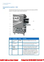
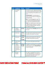
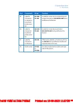
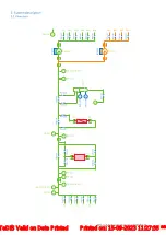
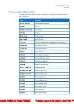
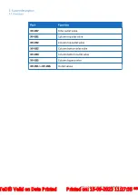
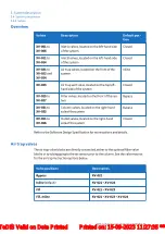

Process component and meters
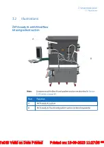
The table below describes the system components and flow kit components shown
in the flowchart.
Part
Function
AE-121/TE-121
pH/temperature sensor
AE-131
UV cell
AE-151 and AE-152
Air sensors
AT-221
Air trap
BA1 to BA6
Buffer A inlets
BB1 to BB4
Buffer B inlets
C1 and C2
Column inlet and outlet, dependent of flow direction
CE/TE-101
Conductivity sensor
CE/TE-102
Conductivity sensor
FE-141
Flow meter cell
LEL-166
Air trap low level meter
LEH-167
Air trap high level meter
P-201.A
Isocratic pump motor
P-201.B
Gradient pump motor
PE-111 to PE-113
Pressure sensors
XV-001 to XV-006
Buffer A inlet valves
XV-011 to XV-014
Buffer B inlet valves
XV-021
Air trap inlet valve
XV-022
Air trap bypass valve
XV-024
Air trap outlet valve
XV-023
Air trap vent valve
XV-025
Filter inlet valve
XV-026
Filter bypass valve
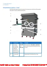
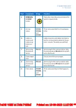
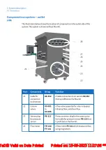
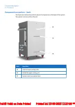
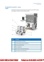
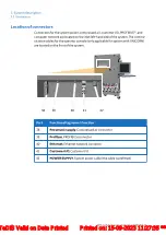
3 System description
3.3 Flowchart
ÄKTA ready XL Operating Instructions 29281616 AE
45
*** TeDIS Valid on Date Printed Printed on: 15-09-2023 11:27:35 ***


