background image

17

AL-2017/AL-3017 Installation Manual

Battery Capacity

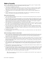
The battery capacity calculations must be performed separately for each part of the system that has a separate AC supply and standby
battery. Use the following steps to determine the correct battery capacities for your system:

1.

Determine the exact configuration of your system.

2.

A separate battery calculation worksheet should be used for each part of the system that has a separate power supply and standby
battery. In the top row of the worksheet, list the primary component (control panel or expansion module) that is powered by the
standby battery. Expansion modules include zone expander modules, relay modules, keypads and card readers.

3.

 On each worksheet, add rows for all expansion modules or other devices that are powered by the primary component on that
worksheet.

4.

On each worksheet, add rows for any type of notification appliance that is connected to corresponding circuits on the primary
component. Also include rows for auxiliary power circuits that have attached devices.

Starting with the first worksheet:

5.

On the row for the primary component, in the total standby current column, enter the current listed for that device. For the control
panel worksheet, this value is 200mA.

6.

On the same worksheet, in any following expansion module rows, enter the operating current for the module in the standby current
column. On all of the expansion module rows, multiply the value in the standby current column by the attached quantity of modules
of that type. Enter the result in the same row, in the total standby current column. If any row contains AL-1191 or  AL-1193 card
readers, enter 80mA in the active current column for that row. Multiply any value in the active current column by the number of
attached card readers, and enter the result in the same row, in the total active current column.

7.

On the same worksheet, in each notification appliance row, enter the alarm current drawn by a single device in the alarm current per
device
 column. On all of the notification appliance rows multiply the value in the alarm current per device column by the number of
devices used on that circuit. Enter the result in the same row, in the total alarm current column.

8.

On the same worksheet, in rows listing devices that are attached to auxiliary power terminals of the primary component, enter the
operating current for each device in the standby current per device column. On all of these rows, multiply the value in the standby
current per device 
column by the number of devices attached to that auxiliary power circuit. Enter the result in the same row, in the
total standby current column.

9.

Repeat steps 5 through 8 for every worksheet.

10. At the bottom of each worksheet, total the values in the total standby current column, the total alarm current column, and the total

active current column.

Perform the following calculations for each worksheet:

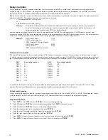
11. Transfer the totaled value at the bottom of the total standby current column to the first blank in formula 1. Enter the required number

of hours in standby in the corresponding blank, and perform the indicated calculation. The result is the standby Amp-hours your
system requires. The value for required number of hours in standby varies by locale. Check with the proper authority having
jurisdiction to determine your requirements.

12. Transfer the totaled value at the bottom of the total alarm current column to the first blank in formula 2. Enter the required number of

minutes in alarm in the corresponding blank, and perform the indicated calculation. The result is the alarm Amp-hours your system
requires. The value for required number of minutes in alarm varies by locale. Check with the proper authority having  jurisdiction to
determine your requirements.

13. Transfer the totaled value at the bottom of the total active current column to the first blank in formula 3. To calculate the required

number of seconds active value, multiply the number of times a card is typically passed by a card reader each hour times the number
of card readers, times 5 seconds.  For a medium traffic area, 12 accesses per hour is a commonly used value (i.e. 5 seconds per
access).

14. Carry the calculated values from the preceeding three steps to the corresponding blanks in formula 4. Perform the calculation to find

the minimum battery capacity requirement for your system.

15. Due to the natural aging effects on batteries over time, temperature cycles, and varying levels of discharge, a derating factor is applied

to compensate for these variables.  Please consult the battery manufacturer data sheets for the appropriate derating factor. Formula 5
shows how to apply a typical derating factor of 1.15 to the minimum battery capacity requirement to determine the actual battery
capacity requirement. The batteries selected for the control panel and for any separately powered expansion modules, must have a
capacity rating that is equal to or greater than the actual battery capacity requirement.

Note:  This system may require two batteries. Each battery must individually meet the actual battery capacity requirement. Do
not mix batteries of different types.

Summary of Contents for Alliance AL-2017

Page 1: ...Alliance Control Panel Installation Manual Models AL 2017 AL 3017 g GE Security ...

Page 2: ...13 Zone inputs 14 Communication options 15 New installer code 15 Relays outputs 16 Battery Capacity 17 Battery calculation worksheet example 18 Absolute maximum loads 18 Battery calculation worksheet 19 FCC Compliance 20 UL Compliance 20 Specifications 22 2009 GE Security All rights reserved No part of this publication may be reproduced transmitted stored in a retrieval system or transmitted in an...

Page 3: ... important to create a comprehensive system plan prior to installing the Alliance system This plan should include a site map a component and equipment list a zone list a type list an area list a region list and the number of users Memory expansion options for the AL 3017 AL 2017 does not support memory expansion AL 1830 memory expansion is a special option installed into the AL 3017 control panel ...

Page 4: ...le female standoffs where threaded holes are aligned with the mounting holes on the control panel and use clip in standoffs where square holes are aligned with the mounting holes Figure 3 3 Install the transformer Mount the transformer in the enclosure using two 6 32 x 1 4 screws provided with the transformer Install the rubber grommet into the transformer shield and mount it to the enclosure usin...

Page 5: ...00VA 12 V battery refer to Battery calculation worksheet for appropriate battery type Chassis ground Enclosure mounting screws Chassis ground connection Earth ground connection Enclosure mounting screw Tamper switch access hole Ferrites Enclosure mounting screw Optional board mounting holes AL 2017 AL 3017 mounting holes AL 2017 AL 3017 AL 2017 AL 3017 Optional boards Optional boards ...

Page 6: ...be checked by a licensed contractor Earth grounding panels in multiple buildings If the wiring extends to separated buildings more than one common earth ground system will be used Use isolater repeaters to isolate the system bus In this way the system is protected against variations in earth potential System bus connection The system bus COMMS is used to connect data gathering panels DGP to provid...

Page 7: ...te Metal chassis must be earth grounded Splice shield drain wire at all juntions Auxiliary power supply connections In systems in which expansion module power is not supplied by the main control panel or an AC powered DGP with auxiliary outputs a UL Listed power supply suitable for burglar alarm applications such as the Altronix AL300ULX must be utilized Note Tie all 0V together Do not connect the...

Page 8: ...IAL07B3 4000 Note We recommend that the system be wired to a dedicated PSTN line Figure 7 PSTN Wiring Diagram AL 2017 AL 3017 control panel Chassis ground Bx Ax B A PSTN connection Tip Green Ring Red RJ31X RJ45 RJ11 12 Premises phone Premises Tip Premises Ring Note A To Pin 5 on RJ45 Cable B To Pin 4 on RJ45 Cable AX To Pin 1 on RJ45 Cable BX To Pin 8 on RJ45 Cable ...

Page 9: ...ponents Power limited wiring Power limited wiring Non power limited wiring Non power limited wiring Optional accessory boards PSTN connection AL 2017 AL 3017 J18 J20 PSTN connection Expansion AC Battery Aux Power Sirens Strobe Bell L1 J1 J7 Kill Comms Tamper Zone inputs RX TX RX TX Modem Comms Control panel wiring connections Figure 9 shows the AL 2017 AL 3017 control panel components and Figures ...

Page 10: ...tal AUX POWER output 300mA including 12 on COMMS Note Alarm output 1 Amp total Siren output must be programmed for DC output if a bell is connected to these terminals instead A 1k resistor must be installed across the external siren outputs Note The first and last device on the system bus COMMS must be terminated Ademco AB12M Note These are dry contacts NEG NC POS NO Note Refer to Battery Calculat...

Page 11: ... battery it will be indicated on the top line of the RAS display If the master RAS powers up but no LEDs lit on and there is not LCD display then no power has been applied to the RAS If the RAS powers up with all LEDs flashing and the display shows System Fault then the system bus cabling may be faulty or the RAS address has been incorrectly set RAS 1 address should be all DIP switches set to OFF ...

Page 12: ...t the panel This option resets all programming to the factory default All programming will be erased and all options will have the standard values To default the panel do the following 1 Press MENU enter 1278 and press ENTER to access the system menu 2 Enter 19 and press ENTER to access installer programming Press MENU advanced menu 3 Enter 14 and press ENTER to access the default option 4 Enter 9...

Page 13: ...and press ENTER The start and end times will display on the top line of the keypad display 9 Press ENTER to advance to the day field 10 Enter 1 through 7 Sunday through Saturday or 8 holiday for each day needed for this time zone and press ENTER Repeat steps 5 through 10 for each access time needed for this time zone four available Areas Program areas to configure individual areas or partitions as...

Page 14: ...pad and press ENTER 11 Select Yes if toggles area status is required and press ENTER 12 Select Yes if enter key opens door only is required and press ENTER 13 Select Yes if door event flag on alarm code is required and press ENTER 14 Select Yes if display shunted zone on LCD is required and press ENTER 15 Select Yes if arm disarm using one key is required and press ENTER 16 Select Yes if card auto...

Page 15: ...crements of 8 to contain up to 32 zones Expanding the number of zones connected to the control panel or a DGP to more than 16 zones by using the AL 1206 is the same as combining two DGP addresses To maintain consistent numbering the additional zones are taken from the next DGP address so you can not include the next DGP address for polling Example An AL 2017 AL 3017 control panel has one AL 1206 8...

Page 16: ...ion does not occur during the PBX dialing string MSN number Microsoft Network For ISDN dialers program a MSN number This number is sent to the ISDN network on dialing o a computer or central station To enter a MSN number use the same method as used for the PBX number Note The MSN number can not contain a 2 second dial pause P or wait for dial tone T Dial tone detection This option enables or disab...

Page 17: ...siren outputs The internal strobe output is always treated as output 2 The internal siren speaker output on the control panel is always treated as output 15 and the external siren speaker output on the control panel is always treated as output 16 On DGPs with siren speaker outputs the last of the 16 output numbers associated with that DGP address is the siren output For example on DGP 3 the siren ...

Page 18: ...he standby current per device column by the number of devices attached to that auxiliary power circuit Enter the result in the same row in the total standby current column 9 Repeat steps 5 through 8 for every worksheet 10 At the bottom of each worksheet total the values in the total standby current column the total alarm current column and the total active current column Perform the following calc...

Page 19: ...tal Maximum auxiliary plus system bus power One 17 2 Ah 500mA 300mA _ _ Absolute maximum loads 1 __________mA X 001Amp mA X _____________ hours ________________ Ah standby Amp hours 2 __________mA X 001Amp mA X ____________ minutes X 0167 hours min _____________ Ah alarm Amp hours 3 __________mA X 001Amp mA X ____________ seconds X 000278 hours sec ___________ Ah active Amp hours 4 Standby Amp hou...

Page 20: ..._____________ hours ________________ Ah standby Amp hours 2 ___________mA X 001Amp mA X ____________ minutes X 0167 hours min _____________ Ah alarm Amp hours 3 ___________mA X 001Amp mA X ____________ seconds X 000278 hours sec ___________ Ah Active Amp Hours 4 Standby Amp hours Alarm Amp hours Active Amp hours Minimum battery power required ________________ ______________ ______________ ________...

Page 21: ...telephone company will notify the customer as soon as possible Also you will be adviced of your right to file a complaint with the FCC if you believe it is necessary The telephone company may make changes in its facilities equipment operations or procedures that could affect the operation of the equipment If this happens the telephone company will provide advance notice in order for you to make ne...

Page 22: ...ypes must be set to 1 see the Alliance System Programming Manual 17 Enable PSTN line monitor must be set to YES see the Alliance System Programming Manual 18 Sirens only after fail to report must be set to NO see the Alliance System Programming Manual Mercantile safe and vault In addition to the above requirements Mercantile Safe and Vault Alarm Systems must comply with the following 1 Alarm sound...

Page 23: ... zone 7 1 14 2 8 34 10 42 Active zone 18 1 11 01 13 8 EOL code 1 4 7 kOhm resistors Status Rzone kOhms Vzone V Active zone 1 02 2 4 4 69 0 Normal zone 3 3 5 2 5 72 7 28 Active zone 7 2 8 34 13 8 EOL code 2 2 kOhm resistors Status Rzone kOhms Vzone V Active zone 1 5 3 4 0 Normal zone 3 0 1 6 3 5 5 1 Active zone 3 1 5 5 13 8 External terminals specifications Values for end of line resistors Current ...

Page 24: ...GE Security 12345 SW Leveton Dr Tualatin OR 97062 503 885 5700 Tech Support 888 437 3287 FaxBack 800 483 2495 www GESecurity com 1052109 B 03 09 ...

Reviews: