


3 Installation
32551-IMG rev 6
GE Healthcare
17
3 Installation
3.1
I
NSTALLATION
OF
THE
COUNTERWEIGHT
WARNING!
If the carriage or counterweight moves resulting cable movement over
the pulley of the vertical motor, there is a risk to damage the pulley or
drive motor assembly (Fig. 2.5). Specifically the fiber gear inside the motor
assembly can be damaged. Please follow the instructions for lifting the
column.
As the column is heavy, it will require at least two people to install it.
1
Move the column crate
into position so that
when the column is
lifted out, it can
immediately be risen
into its final position.
2
Lift the column out of
the crate and rest it on
the C-arm crate with
the center axle pointed
to the bottom. Be sure
to set the column on
some soft material to
prevent scratches.
3
Loosen the bolts
holding the top cap in
position. See
A
in figure
4
Slide the top cap away
from the column. Check
that the cables are not
twisted or crossed.
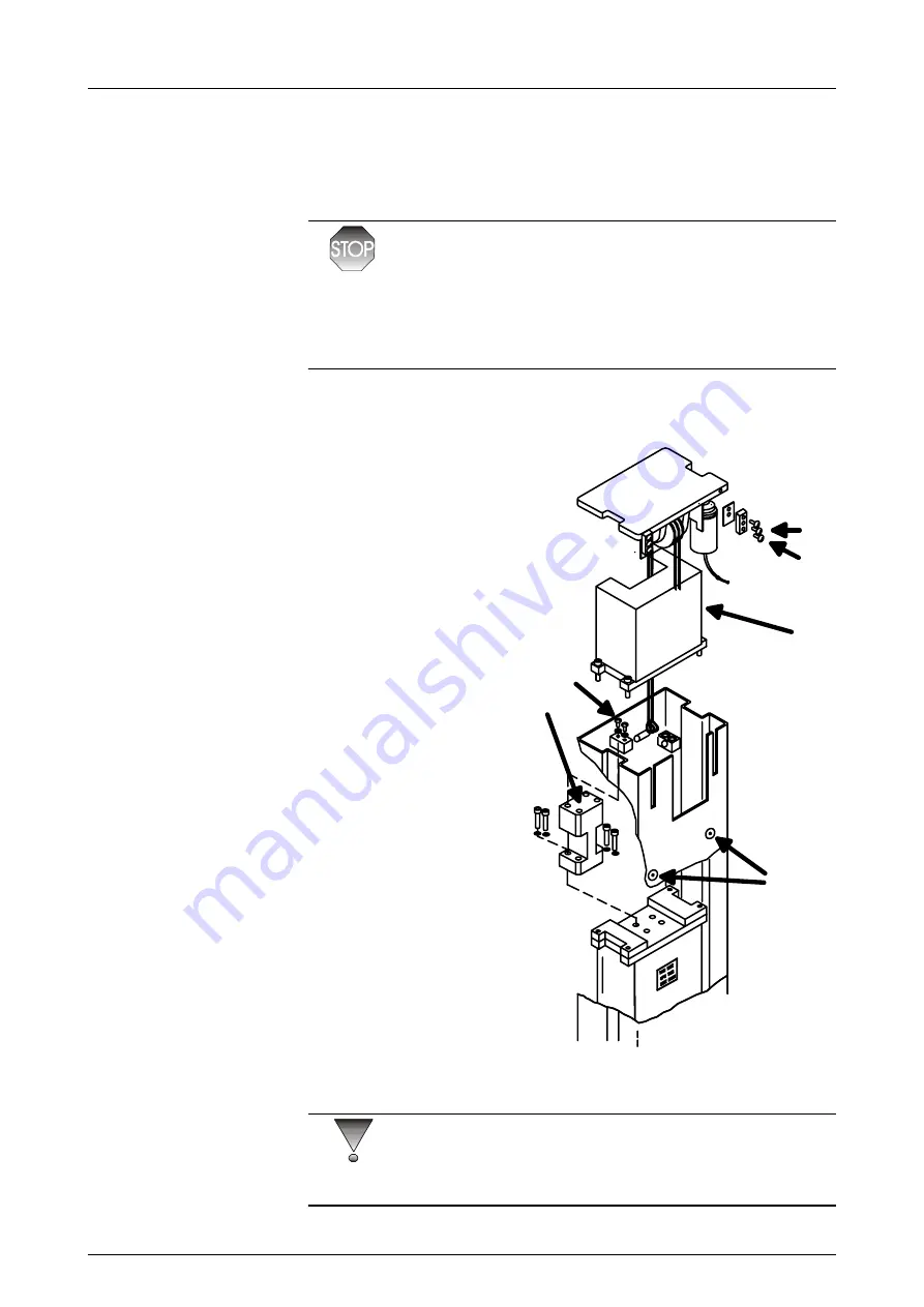
5
Remove the
counterweight
mechanical stop plate
by removing screws B
CAUTION!
Insert the assembly pin through the holes at both sides of the column, and
tape the exposed ends (or use rubber band) to prevent its sliding out.
(D)
A
B
C
(E)
Fig 3.1.
Vertical motor and cables
Summary of Contents for Alpha RT 32551
Page 1: ...GE Healthcare Alpha RT Installation Instructions 32551 IMG rev 6 0459 ...
Page 2: ......
Page 4: ......
Page 42: ...3 Installation 36 GE Healthcare 32551 IMG rev 6 ...
Page 51: ...4 Alpha RT softstart procedure 32551 IMG rev 6 GE Healthcare 45 Fig 4 10 Inverter board ...
Page 52: ...4 Alpha RT softstart procedure 46 GE Healthcare 32551 IMG rev 6 ...
Page 71: ...5 Setups alignments and adjustments 32551 IMG rev 6 GE Healthcare 65 Fig 5 2 Magnetic brake ...
Page 94: ...5 Setups alignments and adjustments 88 GE Healthcare 32551 IMG rev 6 ...
Page 96: ...6 Alpha RT installation step by step 90 GE Healthcare 32551 IMG rev 6 ...
Page 97: ......
Page 98: ......


