3 Installation
22
GE Healthcare
32551-IMG rev 6
7
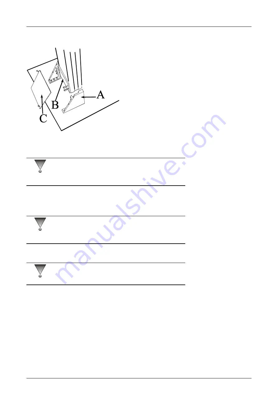
Swing one side plate A into position so that it fits into the groove of
the column (see Figure 3.5, The base plate assembly).
Fig 3.5.
The base plate assembly
8
Slide the pressure plate B into the space between the back of the
column and the flange on the side plate.
CAUTION!
Plate B is not symmetrical and should be installed so that its width
matches the column width. Also notice the slot for the cable.
9
Tighten all bolts and check the column with a water-level. Shift the
column if necessary and tighten slightly the four bolts for the
pressure plate.
CAUTION!
Do not tighten the pressure plate too much since the counterweight might
jam in the lower position. Use for example 3 Nm tightening torque.
10 Assemble the rear cover plate C.
CAUTION!
The back cover plate C will not fit if the column is not in level.
Summary of Contents for Alpha RT 32551
Page 1: ...GE Healthcare Alpha RT Installation Instructions 32551 IMG rev 6 0459 ...
Page 2: ......
Page 4: ......
Page 42: ...3 Installation 36 GE Healthcare 32551 IMG rev 6 ...
Page 51: ...4 Alpha RT softstart procedure 32551 IMG rev 6 GE Healthcare 45 Fig 4 10 Inverter board ...
Page 52: ...4 Alpha RT softstart procedure 46 GE Healthcare 32551 IMG rev 6 ...
Page 71: ...5 Setups alignments and adjustments 32551 IMG rev 6 GE Healthcare 65 Fig 5 2 Magnetic brake ...
Page 94: ...5 Setups alignments and adjustments 88 GE Healthcare 32551 IMG rev 6 ...
Page 96: ...6 Alpha RT installation step by step 90 GE Healthcare 32551 IMG rev 6 ...
Page 97: ......
Page 98: ......


