3 Installation
28
GE Healthcare
32551-IMG rev 6
3.7
A
TTACHMENT
OF
THE
PEDALS
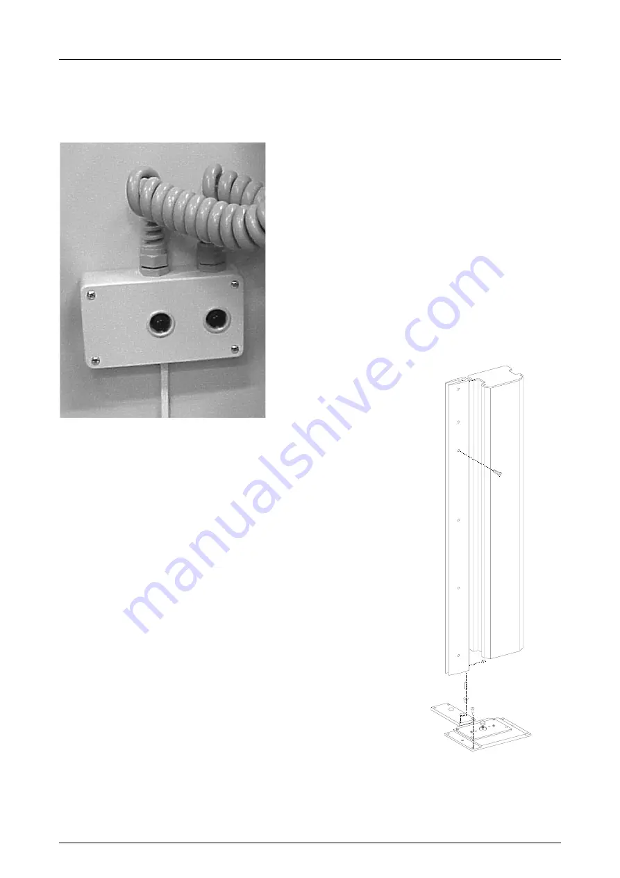
Plug in the footpedals to the connection box in the back of the column.
See figure 3.11, Connectors for the pedals.
Fig 3.11.
Connectors for the pedals
3.8
R
ADIATION
SHIELD
ASSEMBLY
AND
INSTALLATION
Preparations:
Identify how the
Alpha RT
unit is mounted - on stationary base plate or
wall mounted. If the unit is wall mounted, the wall mount base plate is
provided with holes for the hinge support pieces (Fig. 3.12, Wall mount
base plate and hinge support plate).
Instructions:
Open the crate and compare the contents to the packing list. If the
stationary base plate is used, locate the hole provided for the hinge in
base the plate. Drop the sleeve in a hole mount.
Left or right side installation:
1
Press the other plastic sleeve into the large hole on the upper hinge
bracket.
2
Screw the bracket with M6 screws (2) on top of the column.
3
Put the lower hinge pin into the bottom sleeve.
4
Lift the shield into position, and put the upper pin through the upper
hinge bracket into the hinge on the shield.
5
Swing the shield into the desired position. Loosen the shield stop and
lower it until it contacts the floor.
6
Tighten the stop screws. If the wheel is used the adjustment is not
needed.
Fig 3.12.
Wall mount base plate
and hinge support plate
Summary of Contents for Alpha RT 32551
Page 1: ...GE Healthcare Alpha RT Installation Instructions 32551 IMG rev 6 0459 ...
Page 2: ......
Page 4: ......
Page 42: ...3 Installation 36 GE Healthcare 32551 IMG rev 6 ...
Page 51: ...4 Alpha RT softstart procedure 32551 IMG rev 6 GE Healthcare 45 Fig 4 10 Inverter board ...
Page 52: ...4 Alpha RT softstart procedure 46 GE Healthcare 32551 IMG rev 6 ...
Page 71: ...5 Setups alignments and adjustments 32551 IMG rev 6 GE Healthcare 65 Fig 5 2 Magnetic brake ...
Page 94: ...5 Setups alignments and adjustments 88 GE Healthcare 32551 IMG rev 6 ...
Page 96: ...6 Alpha RT installation step by step 90 GE Healthcare 32551 IMG rev 6 ...
Page 97: ......
Page 98: ......


