4 Alpha RT softstart procedure
32551-IMG rev 6
GE Healthcare
39
4.5
R
EMOVAL
OF
THE
BACK
COVER
1
Remove the back cover to expose the circuit boards.
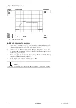
Fig 4.4.
Removing the back cover by opening the four screws
4.6
P
REVENTING
X-
RAYS
(
FOR
EXAMPLE
IN
EXHIBITION
)
NOTE!
The following three items disconnects all power from the generator, but
the system can be still operated. This can be done for example when
installing for an exhibition, where X-rays are not allowed.
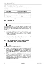
1
Unplug connector X1 on the INVERTER Board (a four-pin connector).
2
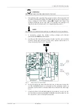
Set the test switches on both the INVERTER Board and the FILAMENT
CONTROL Board to “TEST” position. Set the jumper X8 on the
FILAMENT CONTROL Board to 1-2 position [left-hand position]; (mA
feedback from the filament circuit only).
3
On the FILAMENT CONTROL Board unplug the connector X4 (power to
the filament).
4
Turn
OFF
the unit and plug in the connectors X1 on the INVERTER
board and X4 on the FILAMENT CONTROL board.
5
Set the test switch S1 on the INVERTER board to “NORMAL” position.
– Set the jumper X8 on the FILAMENT CONTROL Board to 2-3
position (right-hand position).
Summary of Contents for Alpha RT 32551
Page 1: ...GE Healthcare Alpha RT Installation Instructions 32551 IMG rev 6 0459 ...
Page 2: ......
Page 4: ......
Page 42: ...3 Installation 36 GE Healthcare 32551 IMG rev 6 ...
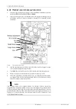
Page 51: ...4 Alpha RT softstart procedure 32551 IMG rev 6 GE Healthcare 45 Fig 4 10 Inverter board ...
Page 52: ...4 Alpha RT softstart procedure 46 GE Healthcare 32551 IMG rev 6 ...
Page 71: ...5 Setups alignments and adjustments 32551 IMG rev 6 GE Healthcare 65 Fig 5 2 Magnetic brake ...
Page 94: ...5 Setups alignments and adjustments 88 GE Healthcare 32551 IMG rev 6 ...
Page 96: ...6 Alpha RT installation step by step 90 GE Healthcare 32551 IMG rev 6 ...
Page 97: ......
Page 98: ......


