4 Alpha RT softstart procedure
40
GE Healthcare
32551-IMG rev 6
4.7
T
RANSFORMER
VOLTAGE
TAPPING
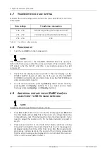
Measure the main voltage and connect the main transformers as in the
table below.
4.8
P
OWERING
UP
1
Turn the unit
ON
from the mains switch.
NOTE!
The “TUBEFAIL” led H3 on the FILAMENT CONTROL Board is usually lit
before the first exposure after the unit is switched on. The activation of the
EXT signal turns the led off, and after a successful exposure the led
remains off.
2
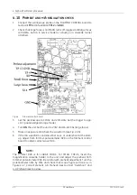
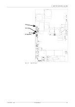
Check that the display shows reset (r.ES in the timer display), on the
POWER SUPPLY board all LEDs are lit (3 pcs), on the FILAMENT
CONTROL board LEDs H8, H9 and H10 are lit, on the INVERTER Board
LEDs H8, H9 and H10 are lit.
3
Go into manual mode by pressing
Autoexp
. Select service mode by
pressing
kV-
and
density-
buttons for 3 sec. Select service mode
menu by pressing
and
Density-
buttons.
4.9
A
NODE
RUN
VOLTAGE
CHECK
(P
R
#57 A
NO
)
OR
ADJUSTMENT
TO
50 H
Z
MAINS
NETWORK
NOTE!
All testing should be performed in service mode.
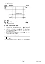
1
Press
kV-
or
kV+
buttons to scroll until the kV display shows
#57
and
the mAs display shows
Ano
. This is the anode run voltage measuring
mode without x-rays. Press Autoexp to enter into Ano program. If you
need to adjust the anode run to 50 Hz mains network, proceed to
step 3.
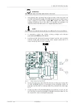
2
Press exposure button to run anode. Timer display will show running
time which is limited to 5 seconds. Check that no error messages are
displayed during that time. After this check that the anode motor
plate stops running (listen to the sound of the rotating anode) and
that no error messages are displayed on Control Panel timer-screen.
If this is not the case, perform step 3.
Main voltage
Transformer connection
198 - 230
220 (factory setting for Europe and U.S.A)
231 - 250
240 (factory setting for G.B and France)
251 - 264
260
Table 4.1 Transformer voltage tapping
Summary of Contents for Alpha RT 32551
Page 1: ...GE Healthcare Alpha RT Installation Instructions 32551 IMG rev 6 0459 ...
Page 2: ......
Page 4: ......
Page 42: ...3 Installation 36 GE Healthcare 32551 IMG rev 6 ...
Page 51: ...4 Alpha RT softstart procedure 32551 IMG rev 6 GE Healthcare 45 Fig 4 10 Inverter board ...
Page 52: ...4 Alpha RT softstart procedure 46 GE Healthcare 32551 IMG rev 6 ...
Page 71: ...5 Setups alignments and adjustments 32551 IMG rev 6 GE Healthcare 65 Fig 5 2 Magnetic brake ...
Page 94: ...5 Setups alignments and adjustments 88 GE Healthcare 32551 IMG rev 6 ...
Page 96: ...6 Alpha RT installation step by step 90 GE Healthcare 32551 IMG rev 6 ...
Page 97: ......
Page 98: ......


