5 Setups, alignments and adjustments
82
GE Healthcare
32551-IMG rev 6
CAUTION!
The AEC is adjusted for one filter and one cassette holder, normally for the
molybdenum filter and with the bucky. The right optical densities for the
rest of the cassette holders with molybdenum filter and for all cassette
holders with rhodium filter are done later as described on
Density
programming
.
5.2.15
Adjusting the AEC board
1
Go to the service program
#64
AEC and check that the AEC Gain
parameter ‘
g
’ is set to
1.00
.
2
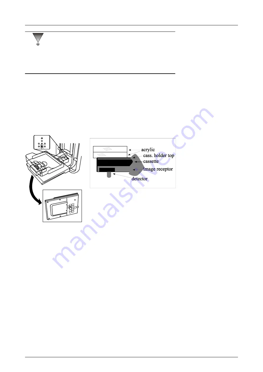
Go back to service mode and make an exposure with semiautomatic
(
A
) mode
28kV
Molybdenum filter @
40 mmAcr
. Use a compression
paddle and a Bucky with a loaded cassette in it. Detector must be in
center position C1. Also, remember to place the white plastic cover
before exposure.
Fig 5.13.
Placement of the acrylics (and phantoms!) onto the cassette holder
3
Press Autorel after the exposure and record the three values
displayed in the mAs window one after one. Each value is displayed
for 1 second. The first value represents the
integration time
(in ms),
the second is
AEC frequency
(for example 320=32kHz) and the last
value is
base frequency
(for example 004=40Hz).
Summary of Contents for Alpha RT 32551
Page 1: ...GE Healthcare Alpha RT Installation Instructions 32551 IMG rev 6 0459 ...
Page 2: ......
Page 4: ......
Page 42: ...3 Installation 36 GE Healthcare 32551 IMG rev 6 ...
Page 51: ...4 Alpha RT softstart procedure 32551 IMG rev 6 GE Healthcare 45 Fig 4 10 Inverter board ...
Page 52: ...4 Alpha RT softstart procedure 46 GE Healthcare 32551 IMG rev 6 ...
Page 71: ...5 Setups alignments and adjustments 32551 IMG rev 6 GE Healthcare 65 Fig 5 2 Magnetic brake ...
Page 94: ...5 Setups alignments and adjustments 88 GE Healthcare 32551 IMG rev 6 ...
Page 96: ...6 Alpha RT installation step by step 90 GE Healthcare 32551 IMG rev 6 ...
Page 97: ......
Page 98: ......


