3 Installation
30
GE Healthcare
32551-IMG rev 6
3.10 T
ESTING
THE
CONTROL
FUNCTIONS
1
Provided that you have all the connectors closed, turn the power of
Alpha RT on. Check that the circuit breaker in the back of system is in
the
ON
position. Switch power
ON
using the main power switch in
the front.
The timer display shows
r.ES
., kV display
Pr
, mAs display
software version
and density display shows the
country code
.
Resetting must be acknowledged by pushing the
auto exp
button, which
starts the internal testing routine.
2
Check that all segments of the 7-segment display and LEDs are lit.
C-arm display
shows the
software version
of C-arm control board.
3
Install a cassette tunnel for normal film/screen imaging,
corresponding diaphragm and a cassette. Notice the
cassette type
:
Normal or Daylight.
Fig 3.14.
Patient identification window in a daylight cassette allows the use of Alpha ID II
or other identification system to print the patient data onto the film.
1
2
3
1 Blue
2 Green/Yellow
3 Brown
Summary of Contents for Alpha RT 32551
Page 1: ...GE Healthcare Alpha RT Installation Instructions 32551 IMG rev 6 0459 ...
Page 2: ......
Page 4: ......
Page 42: ...3 Installation 36 GE Healthcare 32551 IMG rev 6 ...
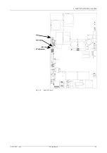
Page 51: ...4 Alpha RT softstart procedure 32551 IMG rev 6 GE Healthcare 45 Fig 4 10 Inverter board ...
Page 52: ...4 Alpha RT softstart procedure 46 GE Healthcare 32551 IMG rev 6 ...
Page 71: ...5 Setups alignments and adjustments 32551 IMG rev 6 GE Healthcare 65 Fig 5 2 Magnetic brake ...
Page 94: ...5 Setups alignments and adjustments 88 GE Healthcare 32551 IMG rev 6 ...
Page 96: ...6 Alpha RT installation step by step 90 GE Healthcare 32551 IMG rev 6 ...
Page 97: ......
Page 98: ......


