5 Setups, alignments and adjustments
76
GE Healthcare
32551-IMG rev 6
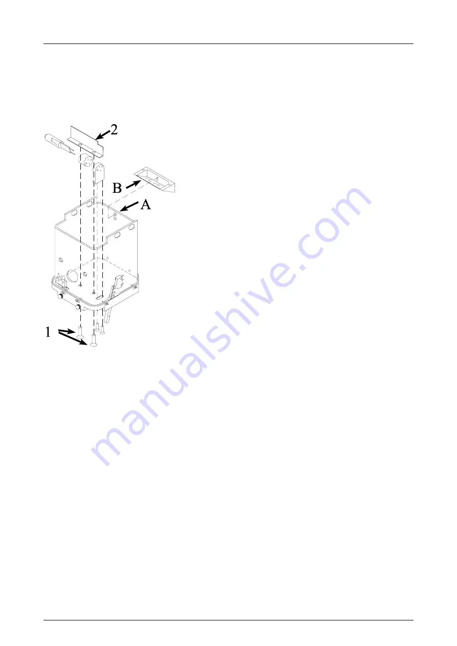
Changing the bulb
1
Remove screws (1) and plate (2).
2
Change the bulb.
3
Reinstall the plate.
4
Adjust the light field. See Fig. 5.11, Light field alignment.
Fig 5.11.
Light field alignment
5.2.13
Grid alignment and speed adjustment (Pr#61 bUC)
The grid is aligned and the speed is adjusted at the factory and should
normally not be adjusted at the site. If adjustment and / or alignment is
necessary, however, follow the instructions below.
1
Remove the carbon fiber cover on the bucky. In the small bucky the
grid should be at the bottom of the grid drive block groove and
fastened with four set screws. In the large bucky the grid should be
fastened only with two set screws and aligned by the two rear set
screws.
2
Check that the grid doesn’t touch the side lips of the bucky and that it
is centered. Check also that the grid is aligned parallel to the side lips.
Speed adjustment
The speed adjustment can be performed by entering the special program
#61 bUC
.
Attach the bucky and enter the program by pressing
Autoexp
. Press the
exposure button to run the grid.
The timer display shows the grid turn-around time which cannot be
adjusted. The mAs display shows the adjustable grid travel time from side
to side.
Summary of Contents for Alpha RT 32551
Page 1: ...GE Healthcare Alpha RT Installation Instructions 32551 IMG rev 6 0459 ...
Page 2: ......
Page 4: ......
Page 42: ...3 Installation 36 GE Healthcare 32551 IMG rev 6 ...
Page 51: ...4 Alpha RT softstart procedure 32551 IMG rev 6 GE Healthcare 45 Fig 4 10 Inverter board ...
Page 52: ...4 Alpha RT softstart procedure 46 GE Healthcare 32551 IMG rev 6 ...
Page 71: ...5 Setups alignments and adjustments 32551 IMG rev 6 GE Healthcare 65 Fig 5 2 Magnetic brake ...
Page 94: ...5 Setups alignments and adjustments 88 GE Healthcare 32551 IMG rev 6 ...
Page 96: ...6 Alpha RT installation step by step 90 GE Healthcare 32551 IMG rev 6 ...
Page 97: ......
Page 98: ......


