GE Power Management
ALPS Advanced Line Protection System
6-7
6 FUNCTIONAL TESTS (USER SETTINGS)
6.3 MEASURING UNIT TESTS
6
SCHEME
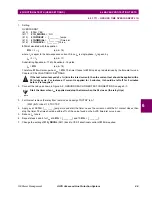
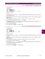
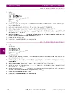
(1201) PICKSCHEME = BLOCK
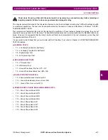
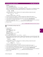
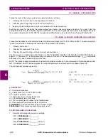
The IPT operating quantity is given by:
(eq. 6–3)
where
I
0
is the Zero-Sequence Current;
I
1
the Positive-Sequence Current; and
KT is 0.1 for Blocking and Hybrid
schemes or 0 for POTT and PUTT schemes. Since the test current,
I
op
, is single-phase,
I
0
and
I
1
are given by
I
0
=
I
op
/3 (eq.
6–4)
I
1
=
I
op
/3
(eq. 6–5)
Substituting Equations 6–4 and 6–5 into Equation 6–3 and assuming a Blocking or Hybrid scheme yields
PUIPT =
I
op
– 0.1
I
op
(eq.
6–6)
= 0.9
I
op
Therefore IPT will pick up when
I
op
= PUIPT / 0.9.
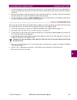
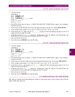
2.
Connect the relay as shown in Figure 4–3: PHASE TO GROUND TEST CONNECTIONS on page 4–12.
3.
Set the voltage inputs to the following values: VA: 55 V rms
∠
0°, VB: 67 V rms
∠
–120°, VC: 67 V rms
∠+
120°
4.
Set the relay into test mode 36 (Ground Directional Trip). The LUI should display: GRD DIR TRIP ON
5.
Set the current of
I
op
to (PUIPT / 0.9) + 0.10 = [_________] amps rms and apply to the relay. The A1 contact should
close. Lower
I
op
to (PUIPT / 0.9) – 0.1 = [_________] amps rms; the A1 contact should open.
6.
Reduce
I
op
to zero.
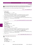
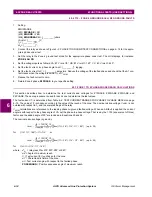
6.3.5 T8 – GROUND DIRECTIONAL BLOCK TEST, IPB + NB
This test applies to blocking schemes only.
1.
Protection Settings:
Z2DISTANCE
(205)
Z2GRDCHAR = GDOC
CURSUPVISN
(503)
IPT_PICKUP = [_________] amps
SCHEME
(1201) PICKSCHEME = BLOCK
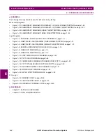
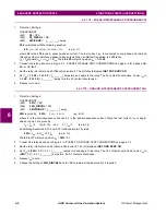
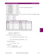
The IPT operating quantity is given by:
(eq. 6–7)
where
I
0
is equal to the zero-sequence current;
I
1
is equal to the positive-sequence current; and
KB is equal to 0.066
for Blocking and Hybrid schemes or 0 for POTT and PUTT schemes. Since the test current,
I
op
, is single-phase,
I
0
and
I
1
are given by:
I
0
=
I
op
/ 3
(eq. 6–8)
and
I
1
=
I
op
/ 3
(eq. 6–9)
Substituting Equations 6–8 and 6–9 into Equation 6–7 and assuming a Blocking or Hybrid scheme yields
PUIPT =
I
op
– 0.066·
I
op
(eq. 6–10)
= 0.934
I
op
Therefore IPT will pick up when
I
op
= PUIPT / 0.934.
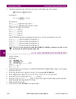
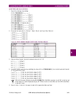
2.
Connect the relay as shown in Figure 4–1: DIGITAL OUTPUTS TEST CONNECTIONS on page 4–9.
3.
Set the voltage inputs to the following values: VA: 55 V rms
∠
0°, VB: 67 V rms
∠
–120°, VC: 67 V rms
∠+
120°.
4.
Set the relay into test mode 37 (Ground Directional Block). The LUI should display: GRD DIR BLK ON
5.
Set the current of
I
op
to (PUIPB / 0.934) + 0.1 = [_________] amps rms and apply to the relay. The A1 contact should
close. Lower
I
op
to (PUIPB / 0.934) – 0.1 = [_________] amps rms; the A1 contact should open.
6.
Reduce
I
op
to zero.
3
I
0
3
KTx I
1
×
–
×
NOTE
3
I
0
3
KB
I
1
×
×
–
×


