


GE Power Management
ALPS Advanced Line Protection System
6-17
6 FUNCTIONAL TESTS (USER SETTINGS)
6.5 ZONE REACH TESTS
6
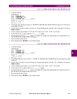
6.5.10 T18 – ZONE 3 PHASE REACH, M3 FAULTS
1.
Protection Settings:
Z3DISTANCE
(301)
Z3PHASE = YES
(304)
Z3GRND = NO
(302)
Z3PHREACH = [_________] ohms,
V
NOM
3
= [_________] V,
I
T
= [_________] A,
øI
3
= [_________]°,
2.
Connect the relay as shown in Figure 5–1: PHASE-TO-PHASE TEST CONNECTIONS on page 5–6 for the appropri-
ate phase under test.
3.
Set the relay to the Zone 3 Phase test mode for the appropriate phase under test. For example: ZONE 3 AB ON
4.
Set the voltage inputs as follows: VA: 67 V rms
∠
0°, VB: 67 V rms
∠
–120°, VC: 67 V rms
∠
+120°.
5.
Set the fault current,
I
op
, phase angle to
øI = [________]°, lagging. Note that the leading phase angle is 180° out of
phase with the line to which it is shorted.
6.
Set the fault current to
I
T
= [________] amps rms. Simultaneously reduce the voltages of the faulted phases, and
check that the A1 contact closes when the voltages are within 7% of
V
NOM
.
7.
Reduce the fault current to zero.
8.
Return Zone 3 ground Z3GRND to your specific setting.
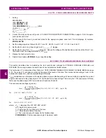
6.5.11 T19 – ZONE 4 PHASE REACH, M4 FAULTS
1.
Protection Settings:
Z4DISTANCE
(401)
Z4PHASE = YES
(405)
Z4GRND = NO
(402)
Z4PHREACH = [_________] ohms,
V
NOM
4
= [_________] V,
I
T
= [_________] A,
øI
4
= [_________]°,
2.
Connect the relay as shown in Figure 5–1: PHASE-TO-PHASE TEST CONNECTIONS on page 5–6 for the appropri-
ate phase under test.
3.
Set the relay into the Zone 4 Phase test mode for the appropriate phase under test. For example: ZONE 4 AB ON
4.
Set the voltage inputs as follows: VA: 67 V rms
∠
0°, VB: 67 V rms
∠
–120°, VC: 67 V rms
∠
+120°.
5.
Set the fault current,
I
op
, phase angle to
øI = [________], lagging. Note that the leading phase angle is 180° out of
phase with the line it is shorted to.
6.
Set the fault current to
I
T
= [________] amps rms. Simultaneously reduce the voltages of the faulted phases, and
check that the A1 contact closes when the voltages are within 7% of
V
NOM
.
7.
Reduce the fault current to zero.
8.
Return Zone 4 ground Z4GRND to your specific setting.
6.5.12 ENDING FUNCTIONAL TESTS (USER SETTINGS)
When testing is completed, verify that all settings are returned to your specified values. It may be helpful to print out the set-
tings and check them one by one.


