2-8
ALPS Advanced Line Protection System
GE Power Management
2.2 GENERAL SETTINGS
2 CALCULATION OF SETTINGS
2
2.2.5 PROGRAMMABLE INPUTS
There are eight contact converters provided in three phase tripping models and twelve contact converters provided in sin-
gle phase tripping models. These contact converters are used to convert contact inputs into logic signals for use within the
scheme logic. Each of the contact converters can be assigned to any of the signals defined by the first 32 Index Numbers
given in Table 2–9 on page 2–51.
Assign any of the 32 signals given in Table 2–9 on page 2–51 to define these contact converter functions.
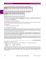
The following contact converter input assignments are recommended when the phase identified channel logic (HYBRIDP)
is used. Note that CC3 and CC4 only need to be assigned when using the four channel scheme.
509: CC9 - Contact Converter 9
510: CC10 - Contact Converter 10
511: CC11 - Contact Converter 11
512: CC12 - Contact Converter 12
(Single Phase Tripping models only)
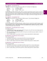
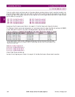
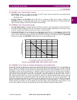
Use any of the 32 signals given in Table 2–9 on page 2–51 to define the function of these contact converters.
501: CC1 - Contact Converter 1
502: CC2 - Contact Converter 2
503: CC3 - Contact Converter 3
504: CC4 - Contact Converter 4
505: CC5 - Contact Converter 5
506: CC6 - Contact Converter 6
507: CC7 - Contact Converter 7
508: CC8 - Contact Converter 8
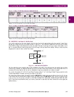
Table 2–6: CONTACT CONVERTER ASSIGNMENT FOR PHASE IDENTIFIED CHANNEL SCHEME
CONTACT CONVERTER ASSIGNMENT
DESCRIPTION
INDEX #
MNEMONIC
501: CC1 - Contact Converter 1
RCVR #1 Input
12
RCVR1
502: CC2 - Contact Converter 2
RCVR #2 Input
13
RCVR2
503: CC3 - Contact Converter 3
RCVR #3 Input
10
STCR *
504: CC4 - Contact Converter 4
RCVR #4 Input
11
BPLTRP *
*Note that Index items 10 (STCR) and 11 (BPLTRP) use mnemonics that refer to their use in the BLOCKING
scheme. When they are used in four channel HYBRIDP scheme logic, they function as the receiver input for the
third and fourth channels.


