2-14
ALPS Advanced Line Protection System
GE Power Management
2.3 PROTECTION SETTINGS
2 CALCULATION OF SETTINGS
2
2.3.3 Z2DISTANCE
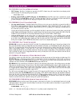
201: Z2PHASE - Zone 2 Phase Distance Function
The choice of settings is YES or NO. Set Z2PHASE = YES if the Zone 2 phase functions are to be used, otherwise set
Z2PHASE = NO.
202: Z2PHREACH - Zone 2 Phase Distance Reach
•
Step Distance Scheme: In this scheme, the Zone 2 functions must be set to see a multi-phase fault at the remote bus,
considering such factors as arc resistance and underreach that may be caused by intermediate fault current sources.
Typically, on a two-terminal line, Z2PHREACH would be set for 125 to 150% of the positive sequence impedance of
the protected line. Z2PHREACH should never be set so large as to:
1.
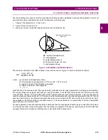
Exceed the maximum allowable reach (
MR), or,
2.
Cause the Zone 2 functions to lose selectivity with the second zone phase distance functions on the shortest
adjoining line section. If this requirement cannot be met by limiting the reach, then it may be necessary to get
this selectivity by setting timer PUTL2P with additional time delay.
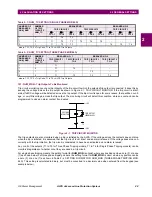
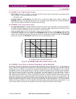
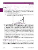
Figure 2–6: OPERATING TIME CHARACTERISTIC
•
Blocking, Hybrid PUTT, POTT1, and POTT2 Schemes: The primary purpose of the Zone 2 functions in any of the
pilot relaying schemes is to detect a fault anywhere on the transmission line and to work with the pilot channel to pro-
vide fast and secure tripping. To this end, the functions must be set to reach beyond the remote terminal of the trans-
mission line and this requirement may be met by setting the functions with a reach of 125 to 200% of the transmission
line. Although the reach requirement would be met with such settings, the operating time might not be at the optimum
when taking into account the operating characteristics of the distance functions as shown above in the diagram above.
For example, if the reach of the Zone 2 functions is set to 125% of line impedance, then the operating time for remote
faults would fall in the area of the upturn of the operating time characteristic, and tripping will be affected accordingly.
On the other hand, if the reach of the Zone 2 functions is set to 300% of the line or greater, then the operating time for
any line fault would fall along the flat part of the time characteristic, and the fastest possible pilot tripping will be
obtained for any fault. It is especially beneficial to use the settings just described on short lines wherein the fastest pos-
sible tripping is required in terms of system stability.
With settings just described, the Zone 2 functions lose their usefulness to provide Zone 2 time-delayed backup protec-
tion since coordination with Zone 2 functions in adjoining lines is not achieved. In that event, the Zone 2 timers can be
turned off or they can be set with a time delay corresponding to Zone 3 time if a third zone of protection is required. To
obtain Zone 2 time-delayed protection, use the Zone 3 functions and set them with a Zone 2 reach (125% of line) and
set the respective Zone 3 timers with a Zone 2 time delay.
In any event, the Zone 2 functions should not be set with a reach any longer than the maximum allowable reach (
MR)
described earlier.
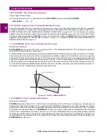
203: Z2PCHARANG - Zone 2 Phase Characteristic Angle
This setting determines the characteristic shape and, consequently, the area of resistance coverage provided by the Zone
2 phase distance functions. Z2PCHARANG can be set to 90° to 120° in 5° steps. A 90° setting is recommended. If the
desired reach, Z2PHREACH, with a 90° characteristic causes the Zone 2 functions to pick up on the maximum load flow,
then a "lens-shaped" characteristic must be used to prevent operation on load without having to reduce the reach. The set-
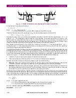
tings of both Z2PHREACH and Z2PCHARANG may be evaluated by using the formula associated with the "Maximum
Allowable Reach" method of Figure 2–5: MAXIMUM ALLOWABLE REACH on page 2–13.
OPERATING TIME
REACH (IN PERCENT)
100

