7-10
This procedure covers the installation of either the right or left motor and
brake assembly.
1. Shut off power.
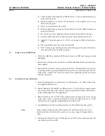
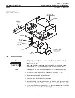
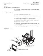
2. Install brake on motor and secure with binding head screws. Be certain brake is
oriented on motor (wires in position to be connected to motor control panel). See
Illustration 7-8.
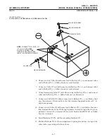
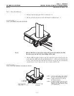
3. Install motor on mounting plate and attach with hex socket head capscrews and
washers.
Motor mounting plate must be oriented with the plate corner bevel toward
the rear. If the Spring Pin was removed from the mounting plate, replace it
and check that it does not rub on the wheel. See Illustration 7-9.
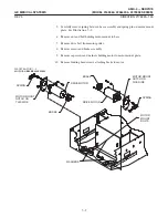
4. Install motor and brake assembly in the base assembly.
5. Attach motor mount to base with nut and motor mount bolt and tighten finger
tight
6. Place drive belt in position on motor pulley.
7. Carefully install spring between base assembly and motor and spring pin on moĆ
tor mount plate. This places tension on the drive belt.
8. Tighten motor mount nut, ensuring the belt tension is not offset by tightening.
Torque to 50-60 foot-pounds (67.8 - 81.3 N-m).
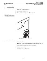
9. Connect motor and brake wire connectors to motor control panel and replace
ty-rap.
J1 - Left Motor
J2 - Right Motor
Use caution when installing brake connector. Connector is keyed but can be
forced on in reverse direction causing brake and possibly printed wire board
damage.
10. Install cassette drawer in frame. Refer to Section 5-2.
Summary of Contents for AMX 4+
Page 1: ...0 0 1 1 2 2...
Page 2: ......
Page 3: ...D D D D D D D D D D D D D D D D...
Page 4: ...D D D D D D D D...
Page 6: ...iv...
Page 8: ...vi...
Page 14: ...xii...
Page 18: ...xvi...
Page 32: ...1 14...
Page 48: ...3 14...
Page 84: ...5 10...
Page 106: ...7 12...
Page 112: ...8 6...
Page 116: ...9 4...
Page 131: ......
Page 132: ...3 2 2 1 0 3 5 0 2 0 4 0 2...

