– 7 –
Upper Control Panel Access
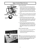
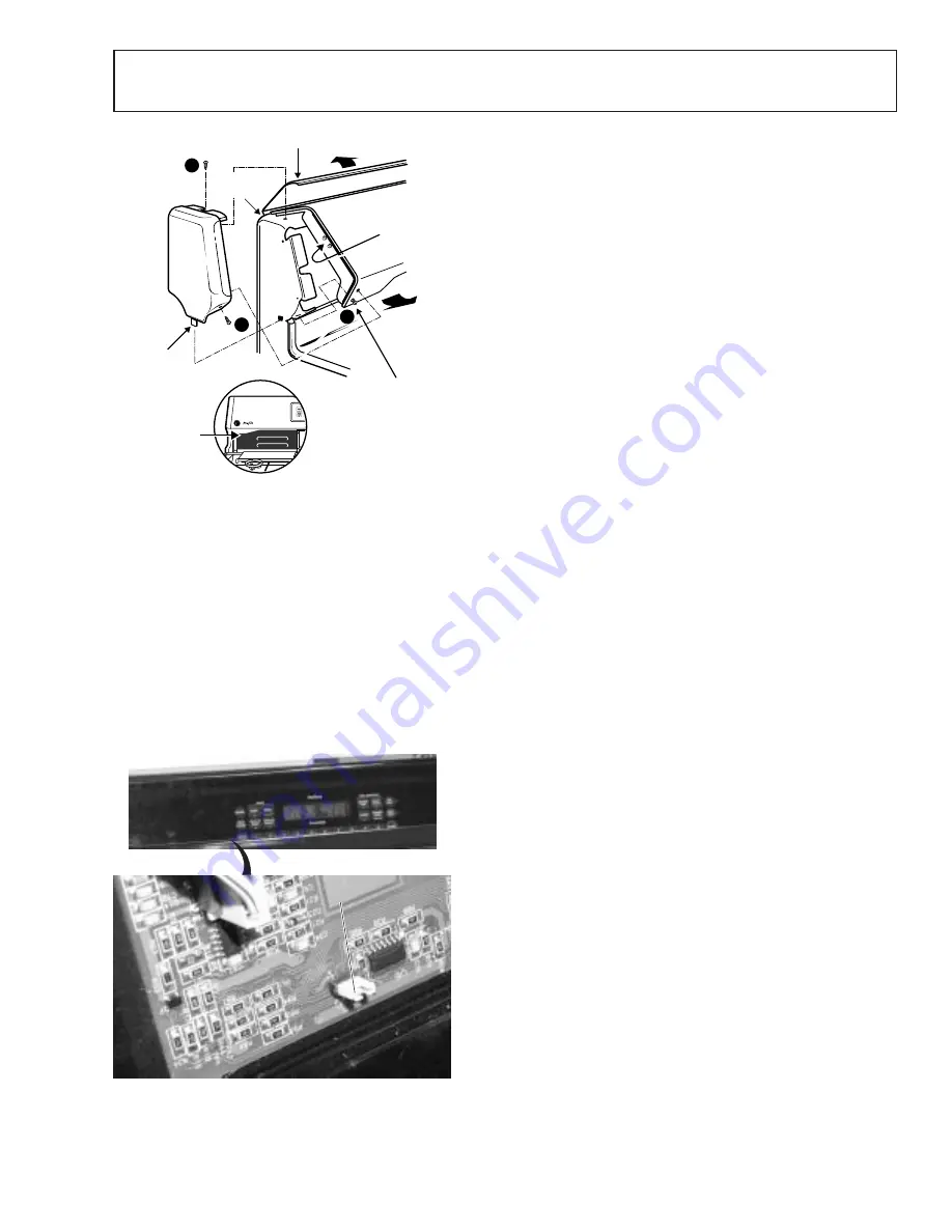
Remove Control Panel
1. Grasp the light panel cover at the rear, where it is
hinged to the control panel. Lift upward at the rear,
just far enough to insert a small, thin bladed screw-
driver between the end cap and the fluorescent light
cover. Be sure to wrap the blade of the screwdriver
with tape to avoid scarring the plastic shield. Slide
the blade forward toward the front while lifting up the
cover.
2. Remove screws (A) and (B) that secure the endcaps
to the control console. Be careful when removing the
endcap not to break the locating tab at the bottom of
the endcap.
3. Loosen screw C 2 turns. This screw is just long
enough that it will protrude into a slot in the side
frame, causing the panel to bind as you slide it down
and forward. Loosening the screw a couple of turns
will back it off enough that it will no longer protrude
into the side frame slot.
4. Grasp the face panel at the bottom front with one
hand, while gently pushing down on the top of the
control panel with your other hand. Pull control panel
downward to release it from the vent deflector while
at the same time pulling the panel forward from the
bottom.
Remove Capacitive Touchpad
1. Remove 2 screws at each end of the control panel.
2. Carefully separate the control panel from the
touchpad to avoid damaging the seal strips above
and below the touchpad.
NOTE: On the circuit board behind the control panel is a
circuit jumper that may fall off during disassembly. When
reconnecting the jumper, be sure to position it on the left
and center pins. Incorrect assembly of the circuit
jumper will result in ECP failure.
HINGED ON
BACK SIDE
FLIP PANEL UP TO ACCESS
FLOURESCENT LIGHT
LOOSEN
THIS SCREW TO
RAISE CONTROL PANEL
BE SURE TAB IS
IN SLOT WHEN
REINSTALLING
REMOVE 2 SCREWS
TO REMOVE TOUCHPAD
A
B
C
SIDE
FRAME
VENT DEFLECTOR
Pull control panel
down and forward to
release it from the
vent deflector
GEA00170
Circuit
Jumper
Summary of Contents for Appliances Profile JGB920
Page 4: ......
Page 5: ......
Page 14: ... 12 Special Features ...
Page 15: ... 13 ...
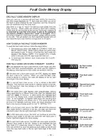
Page 16: ... 14 Fault Code Memory Display ...
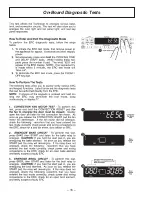
Page 18: ... 16 On Board Diagnostic Tests 1 3 2 ...
Page 19: ... 17 7 4 5 6 ...
Page 20: ... 18 8 ...
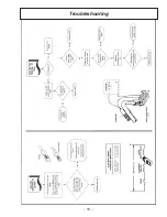
Page 21: ... 19 Troubleshooting ...
Page 22: ... 20 Notes ...
Page 26: ......
Page 28: ... 26 Notes ...


