background image

Arize Element

®

 L1000 Gen2

Horticulture LED Lighting System

HORT162 | DOC-xxxxxxx


WARNING

RISK OF ELECTRIC SHOCK

• 

Turn power off before inspection, installation or removal.

• 

Properly ground electrical enclosure.

RISK OF FIRE

• 

Follow all IEC and local building codes.

• 

Use only IEC approved wire for input/output connections. 

Minimum size 3G 0.75mm

2

.

• 

Minimum 300mm distance from light module & driver to any 

combustible material.

• 

Minimum 150mm clearance between light module & driver, light 

module & light module, driver & driver.

• 

The light module shall be installed lens down with a minimum of 

130mm to anything below.

CAUTION

• 

Do not operate the product with damaged parts.

• 

Turn off power before inspection, installation or removal.

• 

Luminaire may fall down if not installed properly.

• 

Wear work gloves to prevent dirt and oil from being transferred to 

the luminaire.

• 

Not for direct exposure to the weather.

• 

To ensure the product warranty is valid, please ensure all installation 

instructions and environmental conditions for storage and operation 

are complied with. 

•  T

he light source of this luminaire is not replaceable; when the light 

source reaches its end of life the whole luminaire shall be replaced.

•  U

se only in the manner intended by the manufacturer. If you have 

any questions, contact the manufacturer.

•  F

or safe operation, and to maximize the longevity of the luminaire; 

ensure that the light module and driver are clean and free of dirt, 

dust, oil, or any other debris.

•  D

o not apply any kind of film on the lens or otherwise cover the 

driver or light engine in any way.

•  T

he external flexible cable or cord of this luminaire cannot be 

replaced; if the cord is damaged, the luminaire shall be destroyed.

Part Number

220–240 VAC

Power (W)

380–415 VAC

Power (W)

Risk 

Group

Min. Viewing 

Distance (m)

GEHE-HPPRB2A

585

589

2

5.2

GEHE-HPPBB2A

622

626

2

5.2

GEHE-HPKTB2A

606

610

2

5.2

GEHE-HPKRB2A

623

628

2

5.2

GEHE-HPKBB2A

639

643

2

5.2

GEHE-HPKFB2A

643

647

2

5.2

GEHE-HBRIB2A

656

660

2

5.2

GEHE-HBRVB2A

681

684

2

5.2

GEHE-VPPRB2A

530

533

2

5.2

GEHE-VPPBB2A

575

580

2

5.2

GEHE-VPKTB2A

538

542

2

5.2

GEHE-VPKRB2A

569

573

2

5.2

GEHE-VPKBB2A

590

594

2

5.2

GEHE-VPKFB2A

570

575

2

5.2

0°C

40°C

Suitable for operation in an ambient temperature 
between 0

°

C and 40

°

C.

A mechanical ventilation or cooling system is 

required to maintain the temperature within the 

growing space below 40°C when the light module 

is in operation.

IEC/TR 62778 Risk Group 2 (RG2)

DA

Installationsvejledning

DE

Einbauanleitung

ES

Guía de instalación

FI

Asennusohje

FR

Guide d’installation

HU

Felszerelési útmutató

IT

Guida all’installazione

LT

Sumontavimo vadovas

NL

Installatiehandleiding

NO

Monteringsanvisning

PL

Instrukcja instalacji

PT

Guia de Instalação

SE

Installationsguide

220-240V

50-60Hz

380-415V

50-60Hz

IP66

The LED luminaire must be connected to 

the mains supply according to its ratings on 

the product label.

Summary of Contents for Arize Element L1000 Gen2

Page 1: ...vity of the luminaire ensure that the light module and driver are clean and free of dirt dust oil or any other debris Do not apply any kind of film on the lens or otherwise cover the driver or light engine in any way The external flexible cable or cord of this luminaire cannot be replaced if the cord is damaged the luminaire shall be destroyed Part Number 220 240 VAC Power W 380 415 VAC Power W Ri...

Page 2: ...g 2 66 2 67 0 9 GEHE HPKRB2A Arize Element L1000 PKR XW Optic 4 5 kg 2 73 2 74 0 9 GEHE HPKBB2A Arize Element L1000 PKB XW Optic 4 5 kg 2 80 2 81 0 9 GEHE HPKFB2A Arize Element L1000 PKF XW Optic 4 5 kg 2 82 2 83 0 9 GEHE HBRIB2A Arize Element L1000 BRI XW Optic 4 5 kg 2 88 2 88 0 9 GEHE HBRVB2A Arize Element L1000 BRV XW Optic 4 5 kg 2 99 2 99 0 9 GEHE VPPRB2A Arize Element L1000 HE PPR XW Optic ...

Page 3: ...0 universal mounting kit 0 5 kg Description Detailed Description GECA60D16 OL04B AC Leader Cable 1219 mm CE GECA60FNA NL00B AC Field Installable Connector UL and CE Wieland P N 96 031 4155 7 GECA30G14 EN03B DC Inter Connection Cable 914 mm UL and CE GECA30G14 EN06B DC Inter Connection Cable 1828 mm UL and CE GECA30H20 OO03B Dimming cable 914 mm UL and CE Interconnection Cable Specifications Sample...

Page 4: ...stall brackets at location A Press down on bracket until hooks snap into place Ensure bracket hooks catch bottom edge of heatsink Slide down bracket along channels SNAP SNAP If not preassembled install light module brackets on light module 1 1 Installation of Module Brackets 1 3 2 A A ...

Page 5: ...er Based on the cross section of the structural member select the correct hanger or mounting cable 1 2 Selection of Mounting Hardware 1 3 Installation with Standard and Offset Hangers SNAP Use standard hanger 41 mm OR Offset hanger 41 mm to clear the bottom of the Unistrut Use standard hanger 70 mm Use 0 5 m or 1 5 m universal cable OR Perpendicular 90 universal mounting kit Unistrut 41 mm Square ...

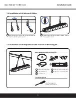
Page 6: ...op end Attach hooks to light module brackets Ensure hook gate is closed Loop Hook 1 5 Installation with Perpendicular 90 Universal Mounting Kit Kits Contents SKU 93139057 Tools Required 1x Worm Drive Clamp 1x Metal Bracket 2x Carabiners 5 16 hex socket or flat blade screwdriver 1828 mm Inter connection 4x 457 mm Universal Cables 1 2 1 2 3 4 1 2 3 4 5 5 ...

Page 7: ...nd wrap the strap around the bottom of the structural member and back up through the second slot Secure the metal bracket on to the top of the structural member by inserting the strap into the open end of the clamp and tightening down the screw Attach a carabiner to each side of the metal bracket Attach a support cable to each carabiner and ensure the gates are closed Attach other end of cables to...

Page 8: ...together slide hook into first driver mounting hole Let driver swing free upright ensure hooks on both sides are correctly engaged Ensure first end of bracket hook is lined up with oval mounting hole of driver Repeat on opposite driver mounting hole If not preassembled install driver bracket onto driver 2 1 Installation of Driver Bracket 1 3 5 2 4 ...

Page 9: ...ver module onto hanger and push down until brackets snap into place Hang driver bracket from one hook then hang other driver bracket end by pressing hanger arms together 2 3 Installation with Hangers SNAP Use standard hanger 41 mm OR Offset hanger 41 mm to clear the bottom of the Unistrut Use standard hanger 70 mm Use 0 5 m universal cable Unistrut 41 mm Square 70 mm Other Structural Members 1 2 ...

Page 10: ...p loop end of cable over structural member Insert hook through loop end Attach hooks to oval driver mounting holes Ensure hook gate is closed If you choose to use your own custom mounting method attach to oval driver mounting holes A and B for hanging No side forces should be applied to mounting holes A and B Loop Hook 1 2 B A ...

Page 11: ... 1828 mm extension cables if driver and light module are more than 0 6 m apart Align keying features of larger output connector on driver with connector on light module cable Push connectors together until the lock ring has snapped into place and a click is heard Recommended secure light module cable 1 2 3 CLICK Driver connections DC Output Dimming AC Input WARNING RISK OF ELECTRIC SHOCK Turn powe...

Page 12: ...Leader Cable Connect 2 beads provided the first bead should be no more than 20mm from input connector 20mm If you choose to use your own custom AC input connection use a Wieland RST20i3 green connector 96 031 4055 7 OR 96 031 4155 7 OR 96 031 0055 7 OR 96 031 1055 7 and plug into the male AC connector of the driver 3 2 4 Connecting Driver to AC Line NOTE To disassemble connectors insert and twist ...

Page 13: ...Blue Dimming Cable Purple Black White 12V Pink Dimming Switch 0 10V 0 10V WARNING RISK OF ELECTRIC SHOCK Turn power off before installation inspection cleaning or removal And follow appropriate lock out tag out safety procedure WARNING Ambient temperature surrounding each driver must be lower than 40 C Remove cap from dimming connector Plug dimming cable align keying features and push connectors t...

Page 14: ...f kablerne til lysmodulet Sørg for at hver eneste krog er helt lukket 1 6 Installation med tilpassede beslag Hvis du vælger at bruge din egen tilpassede monteringsmetode skal du montere ved punkterne A 2 Installation af driver 2 1 Installation af driverbeslag Hvis det ikke er monteret på forhånd skal du installere driverbeslaget på driveren Anbring driveren vinkelret på beslaget Sørg for at den fø...

Page 15: ... am Lichtmodul Stellen Sie sicher dass das Hakentore geschlossen sind 1 6 Installation mit kundenspezifischen Konsolen Wenn Sie Ihre eigene kundenspezifische Befestigungsmethode verwenden möchten befestigen Sie sie an den Punkten A 2 Installation des Treibers 2 1 Installation der Treiberkonsole Falls nicht vormontiert Treiberkonsole am Treiber anbringen Richten Sie den Treiber senkrecht zur Konsol...

Page 16: ...a pieza estructural inserte la cinta en el extremo abierto de la abrazadera y apriete el tornillo Inserte un mosquetón en cada lado del soporte de metal Conecte un cable de suspensión con cada mosquetón y asegúrese de que el pasador está cerrado Conecte el otro lado del cable al módulo de iluminación Asegúrese de que los ganchos están cerrados 1 6 Instalación con soportes a medida Si decide usar u...

Page 17: ...etallikiinnikkeen molemmille puolille Kiinnitä tukivaijeri kumpaankin karbiiniin ja varmista että portit ovat kiinni Kiinnitä kaapelien toinen pää valaisinmoduuliin Varmista että koukkujen läpät ovat kiinni 1 6 Asennus räätälöidyillä kiinnikkeillä Jos päätät käyttää omaa räätälöityä kiinnitystapaasi kiinnitä kohtiin A 2 Ohjaimen asennus 2 1 Ohjaimen kiinnikkeen asennus Ellei ohjaimen kiinnikettä o...

Page 18: ...z un mousqueton de chaque côté du support métallique Attachez un câble de support à chaque mousqueton et assurez vous que les doigts sont fermés Fixez l autre extrémité des câbles au luminaire Assurez vous que les doigts des crochets sont fermés 1 6 Installation avec des supports personnalisés Si vous choisissez d utiliser votre propre méthode de montage fixez la aux points A 2 Installation du dri...

Page 19: ... az A rögzítési pontokat használja 2 A vezérlőegység felszerelése 2 1 A vezérlőegység konzoljainak felszerelése Ha nem lett előre összeszerelve szerelje fel a vezérlőegység konzolját a vezérlőegységre A vezérlőegységet a konzolra merőlegesen kell elhelyezni Gondoskodjon róla hogy a konzol akasztójának első vége egy vonalban van a vezérlőegység ovális rögzítőnyílásával Szorítsa össze a konzol karja...

Page 20: ...re un cavo di supporto a ciascun moschettone e assicurarsi che le leve siano chiuse Collegare l altra estremità dei cavi al modulo luce Assicurarsi che i moschettoni del gancio siano chiusi 1 6 Installazione con staffe personalizzate Se si sceglie di utilizzare un metodo di montaggio personalizzato appendere il modulo nei punti A 2 Installazione del trasformatore 2 1 Installazione della staffa del...

Page 21: ...rie taškų A 2 Maitinimo šaltinio stabilizatoriaus montavimas 2 1 Maitinimo šaltinio stabilizatorius laikiklio montavimas Jei iš anksto nesumontuota pritvirtinkite maitinimo šaltinio stabilizatoriaus laikiklį prie maitinimo šaltinio stabilizatoriaus Nukreipkite maitinimo šaltinio stabilizatorių statmenai laikikliui Pirmasis laikiklio kablio galas turi būti sulygiuotas su ovalia maitinimo šaltinio s...

Page 22: ... de carabiners en zorg ervoor dat de openingen in de carabiners gesloten zijn Bevestig het andere einde van de kabels aan de lichtmodule Zorg ervoor dat de musketonhaken gesloten zijn 1 6 Installatie met custom beugels Als er wordt gekozen voor het monteren met eigen materialen en methode bevestig het element dan aan punt A 2 Installatie van de driver 2 1 Installatie van de driver beugel Indien ze...

Page 23: ...arabinkrok og sørg for at klemmene er lukket Fest den andre enden av kablene til lysmodulen Sjekk at krokklemmene er lukket 1 6 Montering med tilpassede braketter Hvis du velger å bruke din egen tilpassede monteringsmåte fester du til punkt A 2 Montering av driveren 2 1 Montering av driverbrakett Hvis driverbraketten ikke er forhåndsmontert må du montere den på driveren Orienter driveren vinkelret...

Page 24: ...ając śrubę Do otworów po obu stronach elementu metalowego montujemy karabinki Do każdego karabinka mocujemy linki zawieszenia i sprawdzamy poprawność zamknięcia karabinków Wolne końce linek mocujemy do uchwytów modułów lamp Sprawdzamy poprawność zamknięcia zabezpieczeń haków 1 6 Montaż przy użyciu własnych zawieszeń użytkownika Jeżeli wybierasz własną technikę zawieszania to wieszaki należy mocowa...

Page 25: ... as cancelas dos mesmos estão fechadas Prenda as outras extremidades dos cabos ao módulo de luz Certifique se de que as cancelas dos ganchos estão fechadas 1 6 Instalação usando suportes personalizados Se optar por usar o seu próprio método personalizado de montagem ligue aos pontos A 2 Instalação da fonte de alimentação 2 1 Instalação do suporte da fonte de alimentação Se não estiver pré montado ...

Page 26: ... av metallkonsolen Fäst en supportkabel i vardera karbinhake och kontrollera att grindarna är stängda Fäst kabeländarna i belysningsmodulen Kontrollera att krokportarna är stängda 1 6 Installation med anpassade fästen Om du väljer att använda ditt eget installationssätt fäst i punkt A 2 Installation av medbringaren 2 1 Installation med medbringarkonsol Om den inte är förmonterad montera medbringar...

Page 27: ...cordance with local regulations Contact your local authorities or stockist for advice on recycling The packaging material is recyclable Dispose of the packaging in an environmentally friendly manner and make it available for the recyclable material collection service Call us today 1 888 694 3533 Email us arize support gecurrent com Use only in the manner intended by the manufacturer If you have an...

Reviews: