background image

5

6

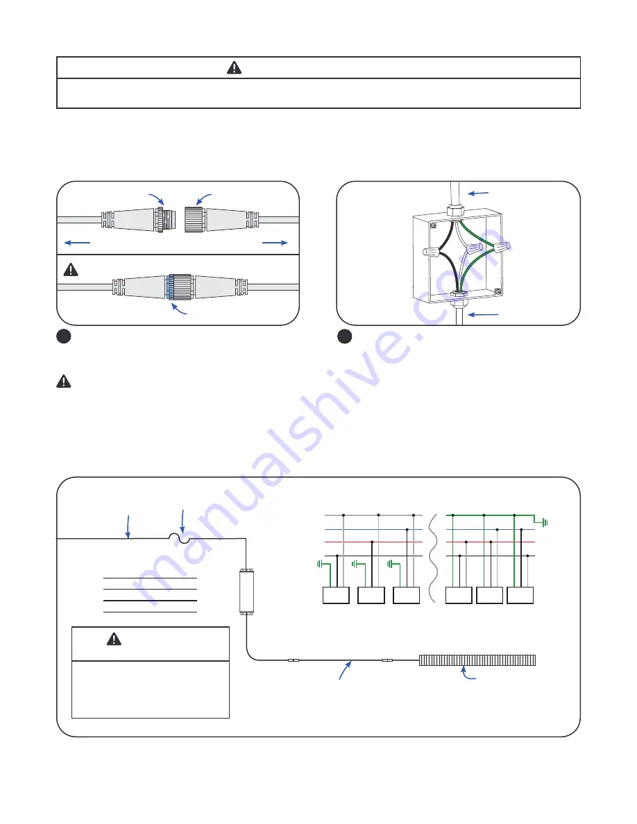
Connect driver input to AC line 
Connect the green wire to the incoming ground 

conductor. Connect the black wire to Line 1 and 

white wires to Neutral or Line 2 of the incoming 

AC line.

Driver Input

Electrical Connections

AC line

To driver input


WARNING / AVERTISSMENT

RISK OF ELECTRICAL SHOCK: Turn power OFF before inspection, installation or removal.

RISQUE DE CHOC ELECTRIQUE: Coupez l’alimentation avant l’inspection, l’installation ou la désinstallation.

5

Connect light module to driver output 
Mate male connector from module with female 

connector from DC output of driver.
Secure blue lock nut by turning counterclockwise 

until tight ensuring water tight seal and good 

connection.

Driver Output 

Electrical Connections

Male

Light module

Secure locknut

Driver

Female

Connection Schematic


WARNING / 

AVERTISSEMENT

Ambient temperature surrounding each 

driver must be lower than 113°F (45°C). 

/ La température ambiante autour de 

chaque module d’alimentation ne doit pas 

excéder 113°F (45°C).

Driver Input  Wire 

Colors

Black = Line 1

White = Neutral or Line 2

Yellow/Green = Ground

Light engine

AC line

Use proper circuit 

protection level

Optional 3’, 6’ or 12’ inter-connection cable

NOTE: Maximum cumulative length of inter-connection cable is 12 feet.

Driver

*White = Neutral or Line 2

*

*

*

Driver

Driver Driver Driver

N

3-Phase Y

REPEAT FOR ENTIRE CIRCUIT BALANCING OUT EACH PHASE

3-Phase ∆

L3
L2
L1

Driver

Driver

Green

Green

Green

Green

Green

Green

Black

Black

Black

Black

Black

Black

White

White

White

White

White

White

Summary of Contents for Arize Element Series

Page 1: ...es locaux applicables Ce produit doit être installé selon le code d installation pertinent par une personne qui connaît bien le produit et son fonctionnement ainsi que les risques inhérents L installation et les structures associées sont soumises à l approbation des autorités compétentes Utilisez uniquement avec les composants identifiés dans ce document Convient aux endroits secs humides et mouil...

Page 2: ... HPKR4 2NX1 Top light 4 ft pink reproductive 646W 120 208 240 277 5 4 3 1 2 6 2 3 0 9 GEHTL HPKB4 2NX1 Top light 4 ft pink balanced 646W 120 208 240 277 5 4 3 1 2 6 2 3 0 9 GEHTL HPKF4 2NX1 Top light 4 ft pink flower 646W 120 208 240 277 5 4 3 1 2 6 2 3 0 9 GEHTL HWTN4 2NX1 Top light 4 ft white industrial 646W 120 208 240 277 5 4 3 1 2 6 2 3 0 9 GEHTL MPKR4 2NX1 Top light 4 ft pink reproductive 34...

Page 3: ...ipe member bracket 2 X 1 3 8 pipe bracket 95047411 GEHAK NN NE N0 Driver universal 1 remote mount kit 2 X 1ft driver support cable 95047654 GEHAK NN NN J1 Wire dimming junction box kit Junction box 2 cable glands 95047660 GEHAK NN NN D1 UL wall mounted dimming switch Dimming switch Accessories ATTENTION ATTENTION Installation instructions and specifications for accessories can be found in the acce...

Page 4: ...und hole on one side of the light module Repeat on other side of light module B Ensure both carabiners are through the hole and both gates are closed Hanging the Light Module NOTE Ensure greenhouse structures and members are rated for loads created by light modules and drivers Suitable min 2 mm diameter suspension cable required to complete installation 4 3 Rotate driver so that the brackets can e...

Page 5: ... water tight seal and good connection Driver Output Electrical Connections Male Light module Secure locknut Driver Female Connection Schematic WARNING AVERTISSEMENT Ambient temperature surrounding each driver must be lower than 113 F 45 C La température ambiante autour de chaque module d alimentation ne doit pas excéder 113 F 45 C Driver Input Wire Colors Black Line 1 White Neutral or Line 2 Yello...

Page 6: ...sure NOTE Be sure to hold on to the screws junction box cover and gasket for future use Wall Dimming Wire Insertion Remove the sealed gland in the top of the junction box enclosure and install an appropriate Listed NPT fitting rated for the environment into the open threaded open conduit connection Bring the conductors for the building dimming network into this fitting NOTE Customer is responsible...

Page 7: ...rticultural luminaires and their placement and or positioning within the plant growth facility It is the responsibility of the plant growth facility to address these risks at the facility level and to ensure that people entering the plant growth areas while the lights are on are aware of these risks and that appropriate safeguards are in place Ces avertissements de sécurité photobiologiques sont b...

Reviews: