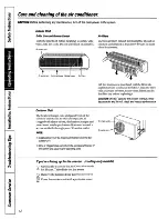
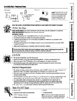
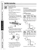
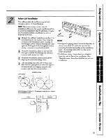
background image

Summary of Contents for AS0CD09 Series

Page 1: ...GEAppliances Cooling Only Models HeutPun Modds ASOCD09 AS1CD09 ASOm09 AS1RD09 ASOCD12 AS1CD12 ASORD12 AS1RD12 ASOCD18 AS1CD18 ASORD18 AS1RD18 Pub No 4 7373 1 CG2 98 ...

Page 2: ...ounds 30 CustomerSeNice Warranty 3l Service Telephone Numbers Back Cover 2 GE You A Service Partnemhip d FOR YOUR RECORDS Write the model and serial numbets hem for the indoor and outdoor units Indoor model Serial Outdoor model Serial You can fmd them on a label on the side of each unit Staple sales slip or cancelled check here Proof of the original purchase date is needed to obtain service under ...

Page 3: ... before it is used be pefiormed by a qualifled individual Be certain the power source is disconnected before servicing the product Since outdoor condensing unit has a sump heater on the compressor for heat pump models the power should be turkd on at For anyservicewhichrequiresentq least 5 hours before unit opemhon Leave into the refrigerantsealedsystem thepower on unless you will not be using the ...

Page 4: ...g operation TIME SETTING BUITONS Used to acjust the time TIMER SEVCANCEL BUTTONS Used to set the timer when the desired time is obtained and to cancel the fimer operation AIRFLOW DIRECTION START STOP BU ON Used to stop or start louver movement and set the desired up down aitilow direction SLEEP MODEAUTO BU ON Used to set Sleep Mode Auto operation AIR CIRCULATION BUTTON Used to circulate the room a...

Page 5: ...ssed and Q stoos when the button is Dressed aaain r OPERATIONMODE SELECT10N U710N o L Used to select the operation mode ROOM TEMPERATURESETTING BUTTONS Used to select the room temperature INDOOR FAN SPEED SELECTOR Used to select fan speed in four steps low medium high orAl TO 5 ...

Page 6: ...ove the batteries from the remote control if Reattach the cover by sliding it back into the system is not going to be used for a long time position Inside the Indoor System Some controls are located inside the indoor unit Open the front panel by lifting it up fVlf a t rafiOn se when the remote control cannot be used Signs ReceptOr eceives the signalsfrom the remote control Operation Indication Lam...

Page 7: ...ct the fan speed in four steps low medium high or AlKU Each time the button is pressed the fa speed mode is shifted Km Q J bY F J aHeating Operation Heat pump model only pJ Press the Start Stop button The unit will respond with a beep Openthedoorontheremotecontrol To selectheatingoperation presstheOpemtionMode Selection button Each time the button is pressed the operation mode is shifted in the ar...

Page 8: ...lly switch from the cooling mode to the heating mode or from heating to cooling it must be done manually Reset using the Operation Mode Selection button L__l Q A During Auto Operation pressing the Airflow g 1A To raise the Direction Start Stop button makes the horizontal temperature louvers swing up and down automatically Ifyou r V want to stop auto swin To lower the temperature press the Airflow ...

Page 9: ... Fin 1 hour for comfortable sleeping Setting the llme Time can be set only when you have pressed the Press the Timer SETbutton Reset button Ifyou havejust replaced the batteries the Reset button should be pressed to reset the time NU7E Check the indicator for A M and PM pJPress the Start Stop button Press the Time Setting buttons until the desired time is set SET 75 Delay Star re Set Stop Make sur...

Page 10: ...f the system Toadjust leiWight direction Adjust the leftiright airflow direction by hand Air Circulation Mode Circulates the room air without cooling or heating mPress the Start Stop button The unit will respond with a beep Opentiedoorontieremotecon ol ResstiefiChcdationbutton Clowtiedoorontieremote control Now each time that you press the Indoor Fan Speed Selector the fan speed is shifted from lo...

Page 11: ...press the Manual Operation button again During Manual Operation the opemting conditions are automatically set as follows holing Only Heat Pump Model Model Room Temp Room Temp Room Temp above X F ZYFttm 76 F below 7V0F Operating Mode I Cooling I Cooling I Dehumidify I Heating I Indoor Fan Speed I High I High I Fan turns on oti automatically I High I Setting Temperature I 72 F I 72 F I Air intake te...

Page 12: ...falter dry before replacing it GAWUIN DO NOToperate the system without a fifter becausedirt andlint will clog it and reducepetiormance Outdoor Unit The heat exchanger coils and panel vents of the outdoor unit should be checked regularly If clogged with dirt or debris the heat exchanger and panel vents may be professionally steam cleaned a service available through your GE service outlet Supply pow...

Page 13: ...ivemal certification I CAUTION Electrical Requirements Be certain all wiring complies with local building codes and NEC and that the supply voltage for this system is correct The system supply voftage is connected to the outdoor unit only Check the rating nameplate on side panel of outdoor unit for required circuit protection rating and required supply voltage Use Underwriters approved electrical ...

Page 14: ...28 of space More than Construct and anchor a strong and level mounting base or pad for the outdoor unit Use the provided rubber grommets between the unit s four mounts and the base or pad ii Anchor the outdoor unit through its four mounts using bolts 5 Rooftop Installations If the outdoor unit is installed on a roof structure be sure to level the unit Ensure the roof structure and anchoring method...

Page 15: ...unt the installation plate horizontally by aligning the centerline using a level Drill the piping hole with a 2 3 hole core drill Drill the piping hole at either the right or the left with the hole slightly slanted to b e outdoor side see illustration below Installation plate Left rear piping 1 1 J J I center 2 3 dia piping hole See templates in the back of this manual for hole location relative t...

Page 16: ...ecommended Gaslineinsu ionWZtion For heat pump models heat resistant insulation material with minimum rating of 230 F is required El See chart on page 14 for maximum lengths of tubing for interconnecting units The indoor and outdoor units are provided with flare nuts See the brass fittings on the indoor outdoor sections N07E The indoor unit is shipped from the factory with a nitrogen holding charg...

Page 17: ...e straight backwards Insertthe connectingwiringcable into the indoor unitfrom the outdoor unitthrough the piping hole 1 Do not connect the cable to the indoor unit 2 Make a small loop with the cable for easy connection later N07E Wtig must comply with local and NEC codes The interconnecting tig between indoor and outdoor units of this system must be 18 4 wiring 18 gauge minim Urn 3oo volt mting ty...

Page 18: ... and right sides of the unit against the installation plate until the hooks engage with their slots clicking sound El hmedng the pipkgs to the indoor unit 1 Align the center of the pipings and sufficiently tighten the flare nut by hand 2 Tighten the flare nut with a wrench af Indoor umt tubing Flare nut Piping El Wrap the insulationmaterial around the connectingportion UJ770N Be careful to arrange...

Page 19: ...easy comection later N07E Wiring must comply with local and NEC codes The interconnecting wiring between indoor and outdoor units of this system must be 18 4 wiring 18 gauge minimum 3oo volt mting type SJO WA or STO WA Tape the tubq drainhose and the connecting cable i i s Gas side piping Liquid side piping Drain hose El Indoor unitimtallation Hook the indoor unit onto the upper portion of the ins...

Page 20: ...cting cable acrossthe back of the ehassk Piping r Tubing holding s retainer Hook L Push l Indoor unit installation Hook the indoor unit onto the upper portion of the installation plate Engage the two hooks of the rear top of the indoor unit with the upper edge of the installation plate Ensure that the hooks are properly seated on the installation plate by moving it left and right netting e Drain h...

Page 21: ...e wire fi om the indoor unit to the outdoor unit size ofwire and wiring method etc Everywire must be cormected securely No wire should be allowed to touch refi igerant tubing the compressor or any moving parts 9K I15V 14 18 15 amps 60Hz lPh 12K 115V 14 18 20 amps 60Hz lPh 18K 230 208V 14 18 I15 amps 60Hz 1 Ph NOES shows field wiring low voltage O shows power source wiring Separately wire the high ...

Page 22: ...end with a wire cutter or wirtiutting pliers then strip the insulation to expose the solid wire about 15 16 Using a screwdriver remove the terminal screw s on the terminal plate Using pliers bend the solid wire to form a loop suitable for the terminal screw Shape the loop wire properly place it on the terminal plate and tighten securely using a screwdriver Solid wire m n r Loop w Q Insulation Fors...

Page 23: ...ss of water on the evapomtor 2 Ensure that water flows through the drain hose of the indoor unit without any leakage and goes out the drain exit the Wiring diagram on page 21 WARNING Be sure to refer to the wiring diagram see Mini Manual Improper tig can cause the unit to opemte incorrectly and result in a tie hazard Check local electrical codes and any spec led wiring instructions or limitations ...

Page 24: ...equivalent around pipings with a gum type sealer Drain hose Trap is required to prevent water from entering into electrical parts 24 H the outdoor unitis being installedabove the position of the indoor uniti 1 Tape the pipings and connecting cable horn down to Up 2 Form the pipings gathered by taping along the exterior wall The trap should be formed up to prevent water from entering into the room ...

Page 25: ... contains 22 charge for the total system Leak Test 1 Connect a manifold valve with pressure gauges and dry nitrogen gas cylinder to the suction semice port 2 Pressurize the system to no more than 150 P S I G with y nitrogen gas and close the cylinder valve when the gauge reading reaches 150 P S I G Next test for leaks with liquid soap lYURION Toavoid nitrogen entering the refrigerant system in a i...

Page 26: ... 5 With a service valve wrench turn the valve stem of the liquid side valve counterclockwise to fidly open the valve Turn the valve stem of gas side valve counter clockwise to folly open the valve Lmosen the charge hose connected to the gas side service port slightly to release the pressure then remove the hose Replace the flare nut and its bonnet on the gas side semice port and fasten the flare n...

Page 27: ...to the Mini Manual supplied with the unit for the systems operating amperage and evaporator discharge air temperature at the various ambient levels At a pical outdoor ambient temperature of 95 the gas suction pressure at the outdoor unit should be 70 75 PS I G in cooling mode For anysavice whichrequiresentry into therefrigerantsealed system Federalregulationsrequirethework be performed by a techni...

Page 28: ...Installation instruction templates I 28 q LeftSideInstallation T Installation plate I I I I ...

Page 29: ...RightSideInstallation Installation plate n m I I I AS ICD09 ASIRD09 AS1CD12 ASIRD12 I I I Piping hole 0 2 3 4 ASICD18 ASIRD 18 29 ...

Page 30: ...irfikerisdi rty Clean the filter at least eveq 30 days See the Operating Instructions section The room may have been hot When the system is first turned on you need to allow or cold tine for the room to cool down or warm up Cold or warm air is escaping Check for open furnace floor registers and cold air returns Theremote control The batteries may be dead Replace the batteries display is faint or s...

Page 31: ...onditioneris of improper cooling capacityfor the intended use contactyour dealer or installer You are responsible for providing adequate electricalcomecting facilities Failureof the product resultingfrom modifkations to tbe product or due to unreasonableuse includingfailure to provide reasomble and necesszuymaintenance In commercial locations labornecessaryto move the unit to a location where itis...

Page 32: ...gerant system must be performed only by a licensed w HVAC cefiled technician i Instructions contained in this manual coverprvcedures to be perfbrmed by any usez lthersem cing generally should be retiwmd to qualified service pemonnel Cautionmust be exemised since I imprvper sem cing may cause unsafa operation E g br anysem ce which requires entry into the retiigemntsealed system hderal regulti ons ...

Reviews: