background image

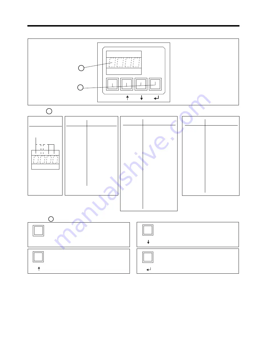
4-1. Keypad and Display description

1

2

Display

1

F

V

V

V

F V V V

Error code

E 0 1 0

Frequency out of range

E 0 1 1

Overload trip

E 0 1 3

Loss of synchronism

E 0 1 4

Phase U scr

E 0 1 5

Phase V scr

E 0 1 6

Phase W scr

E 0 1 7

Heatsink overtemperature

E 0 1 8

Motor thermistor

E 0 1 9

Phase U lost

E 0 2 0

Phase V lost

E 0 2 1

Phase W lost

E 0 2 2

Stalled rotor

E 0 2 3

Internal error

E 0 2 5

Long start time

E 0 2 6

Long slow speed time

E 0 2 7

Lock-out

E 0 2 8

Undervoltage

E 0 2 9

Overvoltage

E 0 3 0

Undercurrent

E 0 3 1

Overcurrent

E 0 3 2

Retry, attempts exceeded

F V V V

Status code

O N

Equipment is connected

to main supply

(equipment is ON)

S T O P

Stop

L O C K

Remote stop

P U L S

Kick start

R A M P

Acceleration ramp

F U L L

Full conduction or

Override

S A V E

Energy saving

S O F T

Soft stop

P U M P

Pump control

D C B K

DC braking

I N C H

Inching / slow speed

T A C H

Linear ramp (tacho)

Keypad

2

SELECTION

Use with


↑↑↑↑↑


or


↓↓↓↓↓


to select the parameter or function code to be

displayed and/or modified

SEARCH / ADJUSTMENT

Increases the value of the selected parameter

ENTER / SAVE

- Introduces the new parameter value into memory

- Updates the selected parameter value with the

displayed value

SEARCH / ADJUSTMENT

Decreases the value of the selected parameter

1

1

4

3

2

0

C / V

Data

Function code

C / V

4-1

4. Programming

Displays Monitoring, Status indications, error messages and function set values

Allows setting of parameters and functions

F F/V V V

function code (*)

M x x x

Motor current

v x x x

Software Version

.

.

.

.

P F x x

Power Factor

.

.

.

.

L x x x

Limit current

T x x x

Starting Torque

a x x x

Ramp up time

d x x x

Ramp down time

S x x x

Soft Stop selection

.

.

.

.

L K x x

Lock out

.

.

.

.

(*) These are examples. Full details in

sections 4-2, 4-3, 4-4, 4-5 and 4-6

Display Structure

Summary of Contents for ASTAT Plus

Page 1: ...sure that this manual is delivered to the end user 3 CE Marking When using ASTAT Plus in the EU compliance with EMC is required ASTAT Plus range comply with the generic EN 50081 2 and EN 50082 2 2 The policy of GE Power controls is one of continuous improvement The right is reserved to alter the design on any structural details of the products at any time without giving notice ...

Page 2: ...r protection CAUTIONS 1 Semi conductor fuses specified may not provide branch circuit protection Refer to local applicableelectricalcodes 2 Overload relay setting should be properly coordinated with motor 3 Slow speed running will affect the motor thermal characteristic due to reduced cooling Care must be taken when operating motor under these conditions 4 DC braking braking current may cause moto...

Page 3: ...caracteristiques thermiques à cause de la réduction de refroidessement Opérez le moteur avec précaution dans en ce cas 4 Ralentissement courant continu peut provoquer la surchauffe de moteur Choisissez le plus foible courant de décéleration et la durée de ralentissement la plus courte 5 Pour freinage courant continu un contacteur DC3 additional est nécessaire dans le circuit moteur voir le schéma ...

Page 4: ...3 3 3 4 Operating modes 3 4 Section 4 Programming 4 1 4 1 Keypad and display description 4 1 4 2 Parameter configuration 4 2 4 3 Monitor block parameters 4 4 4 4 Calibration block parameters 4 5 4 5 Basic block parameters 4 6 4 6 Advanced block parameters 4 7 Section 5 Installation 5 1 5 1 Equipment installation 5 1 5 2 Fuses contactors and supply wiring 5 2 5 3 Start up 5 3 5 4 Troubleshooting 5 ...

Page 5: ...onadjust current in the line max 90 of direct start torque 100 30 40 or 64 33 49 48 33 Depending on adjust max 90 Starting steps 1 1 4 3 or 2 3 or 2 2 2 Continuous no steps Connections to motor 3 3 3 6 6 3 Line overload 5 In 1 5 2 1 or 3 2 In 3 3 5 In 3 25 In 1 65 In Depending on adjust approx max 4 7 In Change or NO NO NO NO YES NO starting pause 1 Steps mean sharp changes of speed during the tim...

Page 6: ...ar acceleration ramp forwardandreversejog programmableI O orconnectiontoacomputerbyserial communication RS 232 all included as standard These performances allows the incorporation of the soft starter to a distributed control net in automated plant processes together with other soft starters programmable controllers variable speed drives etc Pump control The ASTAT Plus includes a Pump Control funct...

Page 7: ...P 45 0 99 20 Byfan 240 63 110 132 288 80 150 165 IP 00 QC1QDP 45 0 99 20 Byfan 63 110 132 160 80 150 165 200 IP 00 QC2QDP 45 0 99 20 Byfan 315 90 160 200 378 110 200 220 IP 00 QC1RDP 55 0 121 3 Byfan 90 160 200 220 110 200 220 250 IP 00 QC2RDP 55 0 121 3 Byfan 370 110 200 220 444 132 220 250 IP 00 QC1SDP 55 0 121 3 Byfan 110 200 220 250 132 220 250 315 IP 00 QC2SDP 55 0 121 3 Byfan 475 150 250 250...

Page 8: ...an 40 40 IP 00 QC2KDP 12 5 27 56 Byfan 72 360 20 20 20 25 IP 00 QC1LDP 17 0 37 48 Byfan 40 50 IP 00 QC2LDP 17 0 37 48 Byfan 105 525 30 30 30 30 IP 00 QC1MDP 17 0 37 48 Byfan 60 75 IP 00 QC2MDP 17 0 37 48 Byfan 156 780 40 50 50 60 IP 00 QC1NDP 45 0 99 20 Byfan 100 125 IP 00 QC2NDP 45 0 99 20 Byfan 240 1200 60 75 75 75 IP 00 QC1QDP 45 0 99 20 Byfan 150 200 IP 00 QC2QDP 45 0 99 20 Byfan 315 1575 75 1...

Page 9: ...e time for cool down is 300 sec after the overload trip Ifthecontrolvoltageisremovedaftertripping youmustwait atleast 2 minutes before the unit can be restarted Operations per hour Supposing a cycle T with starting time of t1 running time of T 2t1 at rated current and OFF time of t1 sec at least the ASTAT Plus allows the following operations per hour Starting Operations Hour Operations Hour Curren...

Page 10: ...dback Outputs 3 programmable relays 1r 2r 3r 1 Analog 0 10VDC output for current metering Protections Current limit Adjustable from 1 In to 7 In Overload IEC class 10 and 20 NEMA class 10 20 and 30 all selectable Cool down time after overload trip s 300 for reset Loss on input phase s Trip at 3 Thyristor short circuit ms Trip at 200 Heatsink overheating ms Trip at 200 Motor thermistor ms Trip at 2...

Page 11: ...gned to function RUN 23 24 Programmable relay 2r 23 24 N O dry contact This relay can be assigned to several internal output functions page 3 6 As default assigned to function EOR 33 34 Programmable relay 3r 33 34 N O dry contact This relay can be assigned to several internal output functions page 3 6 As default assigned to function DC BRAKE Common for all relay output contacts Maximum usage volta...

Page 12: ...ng recommendations are given in chapter 5 2 The programmable inputs I3 I4 are not assigned to any function as default Check pages 3 6 prior to using these inputs 3 The programmable relay outputs are assigned to the following functions as default Relay 1r RUN RUN status Relay 2r EOR End of Ramp Relay 3r DCBR DC Braking control 4 Important Use dry contacts only 3 3 4 4 ...

Page 13: ...peedrampbytachofeedbackalsopossible Fastincreaseofoutputvoltagewhenmotorgetsratedspeed 1 to 7 In Ratedvoltage Override Ratedcurrent Energy savings Enabled by Fxxx to OFF Motor power cut off Sxxx to OFF Cxxx to OFF Decelerationramp1to120s adjustable Secondaryramp1to99s Rampdowmmodesavailableare Soft Stop Voltage ramp down Enabled by Sxxx to ON Pump control Selectable by Sxxx to ON and Cxxx to ON Li...

Page 14: ... Enabled by parameter Jxxx to ON and rxxx to ON Slow speed 7 or 14 Enabled by parameter Jxxx to ON Accelerationramp Ramptimeadjustable Softstop decelerationramp Ramptimeadjustable Slow speed 7 or 14 Enabled by parameter Jxxx to ON DC Brake Current and time adjustables Enabled by parameter Bxxx to ON and bxx Ixxx adjustments 1 8 7 6 5 4 3 2 LinearrampwithT G feedback Slowspeed Basicdiagram Slowspee...

Page 15: ...l functions as shown bellow Relay 1r Relay 2r Relay 3r 20 21 22 23 24 25 26 27 28 29 30 EOR Detects end of voltage ramp Only can be asigned to relay 2r DC Brake DC Brake command Only can be assigned to relay 3r Fault Detects ASTAT s fault status Undervoltage Detects limit set in parameter UVxx Overvoltage Detects limit set in parameter OVxx RUN Detects ASTAT s run status JOG Detects Jog slow speed...

Page 16: ...E Energy saving S O F T Softstop P U M P Pumpcontrol D C B K DC braking I N C H Inching slow speed T A C H Linearramp tacho Keypad 2 SELECTION Use with or to select the parameter or function code to be displayed and or modified SEARCH ADJUSTMENT Increasesthevalueoftheselectedparameter ENTER SAVE Introducesthenewparametervalueintomemory Updates the selected parameter value with the displayed value ...

Page 17: ...L GADV and GALL values repeatedly The actual value displayed can be stored in a temporal memory buffer by pressing key Values stored in the temporal memory are lost upon control power loss unless these are saved in the permanent E2PROM memory through parameter W Additional indications are given in page 4 4 The above is an example given for parameter G but all ASTAT Plus parameters can be modified ...

Page 18: ...utput relay 1r Output relay 2r Output relay 3r 100 700 010 090 01 99 01 120 000 999 000 099 050 250 OFF ON I3 I4 OFF ON I3 I4 00 05 OFF ON I3 I4 OFF ON I3 I4 OFF ON I3 I4 PON PI3 PI4 00 45 ON OFF ON OFF 000 004 001 099 00 50 00 99 00 30 00 99 00 99 00 99 00 50 00 99 01 99 01 99 10 90 ON OFF I3 I4 OFF I3 I4 LO HI OFF ON I3 I4 OFF ON I3 I4 OFF ON I3 I4 22 30 20 22 30 21 22 30 L T a d p b I S C P F z...

Page 19: ...d in kA If parameter UFxx is not calibrated the motor current is displayed in N xxx Version number Displays line voltage in Volts Displays line Power Factor Displays Line Power Displays RUN time in Hours x 1000 Saves the last four errors e0xx Fault 1 Latest fault xx Fault code error e1xx Fault 2 e2xx Fault 3 e3xx Fault 4 69 allows E2PROM writing operation 10 Key lock enabled 20 Key lock disabled S...

Page 20: ...p to 3 proceed as follow 1 Switch on the ASTAT and measure the RMS voltage on phases 1L1 3L2 using a calibrated voltmeter 2 Search the parameter txxx set the voltage measured and save this value by the key It is not necessary to rewrite the E2PROM to make permanent the new setting the ASTAT plus does this automatically NOTE Set real voltage measured while ASTAT is Power ON DO NOT enter motor namep...

Page 21: ... Pump Curve selection at starting phase Pump Curve selection at stopping phase Kick Start selector Override selector S x x x C x x x S T X X S P X X P x x x F x x x S O F F C O F F S T 0 0 S P 0 2 P O F F F O F F Enables or disables all modes of Soft stop Enables the Pump control function Usefull to limit fluid hammering The parameter Sxxx must also be enabled NOTE Parameters p b and I are disable...

Page 22: ... x L K 0 0 R O F F Q O F F Y 0 y 1 0 U V 0 0 u v 2 0 O V 0 0 o v 2 0 U C 0 0 u c 2 0 O C 0 0 o c 2 0 2 a 2 0 2 d 2 0 2 T 2 0 Sets time between consecutive starts Setting 0 disables this function Loads the parameters from the E2PROM to the temporal buffer Loads default factory settings to the temporal buffer Allows up to four tries of automatic restart after a fault Setting 0 disables this function...

Page 23: ...ON I3 I4 OFF ON I3 I4 00 02 001 247 Function Display Description Default Range 4 6 3 Programmable Relay Output Functions Output relay 1r Output relay 2r Output relay 3r 1 r x x 2 r x x 3 r x x 1 r 2 5 RUN 2 r 2 0 EOR 3 r 2 1 DC Brake This is a programmable relay with one NO NC dry contacts to ASTATPlus sterminals11 12 14 This is a programmable relay with one NO dry contact to ASTAT Plus s terminal...

Page 24: ... contactors located in the same housing as the equipment should haveanRCsuppressorparalleltothecoil orareversediode ifcontroledbyDC Do not install capacitors to correct the power factor between equipment output and motor Iftheequipmentisfedbyalinetransformer itsratedpowershouldbeatleast1 5 times but less than 10 times higher than equipment supply A C D C SIGNAL POWER 5 Installation Environment Whe...

Page 25: ...6 6 URD 30 XX 0250 00 250 2 55 CL10 CL06 35 QC _ N DP 156 591 200 6 6 URD 30 XX 0315 00 315 2 78 CK75 CL07 70 QC _ Q DP 240 901 315 6 6 URD 31 XX 0500 2 550 2 78 CK85 CK75 120 QC _ R DP 315 1063 400 6 6 URD 31 XX 0630 2 630 4 118 CK95 CK85 185 QC _ S DP 370 1136 500 6 6 URD 32 XX 0800 2 800 4 118 CK10 CK85 240 QC _ T DP 475 1721 630 6 6 URD 33 XX 1000 3 1000 4 118 CK11 CK95 Bus bar 1 QC _ U DP 610...

Page 26: ...f B enabled I 5 0 Set braking parameters as needed Set overload trip curve as needed Set starting parameters as needed Set parameter K to ON ON 69 Set parameter W to ON Press parameter W is set to OFF automatically If you change the default configuration and wish to keep it remember to rewrite the parameters in E2PROM as follows Send run command to equipment and make sure that operation is correct...

Page 27: ...limit and or acceleration ramp time Current limit condition present more than 2 x ta sec or 240 sec ta acceleration ramp time 5 Installation S L 10 ohms 3 to 6V 3 to 6V Testing lamp 1L1 3L2 or 5L3 2T1 4T2 or 6T3 5 4 5 5 Thyristor check Shortcircuit Use a testing lamp to check the defective power module between input and output phases If the lamp goes on at least one of the thyristors has a shorcir...

Page 28: ...actionon contactors according ratings specified in page 3 2 of this manual 4 CAUTION In by pass mode an external overload re lay protection must be used 5 By pass control using function zxxx and externalcontactorDC2 Detailsgivenbel low By pass control Programming steps 1 The by pass function may be enabled by setting zxxx to ON In this case the by pass is automatically done after starting An alter...

Page 29: ...lation from the incoming line increasing the safety 2 In this example Start and Stop command is enabled by permanent command Push buttons control is allowed as well wiring 1 2 and 57 terminals as shown in page 3 3 3 The output relays allow for direct action on contactors according ratings specified in page 3 2 of this manual 4 The ASTAT Plus is provided with an electronic motor overload protection...

Page 30: ...he applications You should use an external overload protection if required by local codes or to protect the motor against current unbalance 5 Linearrampprovidedby Dxxx function A tachogenera tor must be used as feedback Details given bellow Linear ramp function Programming steps 1 The linear ramp function may be enabled by setting Dxxx to ON In this case linear ramp is independent of the load This...

Page 31: ...cation possibilities are available Connection to a PC PLC using ASCII protocol PC Windows communication software tool available Connection to a PC PLC using Modbus RTU protocol Connection to industrial fieldbus systems Profibus DP DeviceNet In this case it is necessary to use an external communications module Astat Plus communicates with this module using Modbus RTU protocol and the module acts as...

Page 32: ...and will be 02W060000 to stop the unit the command will be 02W060001 to set the acceleration ramp time to 35sec the command will be 02W005035 to know which overload curve is selected the command will be 02R016 if for instance the response is 02R01600004 this means that the overload curve selected is IEC class 10 The Table shown in 6 2 5 provides a complete reference for the parameters that can be ...

Page 33: ... will not execute the command Only the slave with the corresponding address will send a response message Function code as related above Write command is number 10h Data Field as this is a write command the data requested is the number of parameters to be written number of chars starting address and the value to write Quiet time Slave Address Function Code Data Field CRC Quiet time starting address...

Page 34: ...unction Code Data Field CRC Quit Time 0003 3 5 chars 11 03 0004 2 chars 3 5 chars To write values 1 2 and 3 in parameters 9 10 and 11 Quiet Time Slave Address Function Code Data Field CRC Quit Time 0009 3 5 chars 11 10 0003 2 chars 3 5 chars 06 0001 0002 0003 To execute the above 2 commands in one Quiet Time Slave Address Function Code Data Field CRC Quit Time 0003 3 5 chars 11 17 0004 2 chars 3 5...

Page 35: ...ribed in chapter 4 All data communication with the ASTAT will be done through the fieldbus input and output data areas in the Communication Adapter being the address of these areas the following Input data address parameter number 0000h 0079h 0d 121d used to read parameters Output data address 1000h parameter number 1000h 1079h 4096d 4217d used to write parameters Examples to read the T parameter ...

Page 36: ...c R W 1 120 7 p Kickstarttime msec R W 0 999 8 b DC brake time sec R W 0 99 9 I DC brake current In R W 50 250 10 S Softstopcontrol R W 0 3 0 OFF 1 ON 2 I3 3 I4 11 C Pumpcontrol R W 0 3 0 OFF 1 ON 2 I3 3 I4 12 P Kickstartcontrol R W 0 3 0 OFF 1 ON 2 I3 3 I4 13 F Override R W 0 3 0 OFF 1 ON 2 I3 3 I4 14 B DC brake control R W 0 6 0 OFF 1 ON 2 I3 3 I4 4 PON 5 PI3 6 PI4 15 LK Lockout min R W 0 45 16 ...

Page 37: ...KW 10 R 42 X Local remotecontrol 0 3 0 OFF 1 ON 2 I3 3 I4 43 D Linear ramp control R W 0 3 0 OFF 1 ON 2 I3 3 I4 44 J Slow speed control R W 0 2 0 OFF 1 I3 2 I4 45 j Slow speed type R W 0 1 0 HI 1 LO 46 2a Secondary acceleration ramp time sec R W 1 99 47 2d Secondary deceleration ramp time sec R W 1 99 48 A Dualrampselection R W 0 3 0 OFF 1 ON 2 I3 3 I4 49 UF Unitframe R W 0 16 0 not defined 1 to 1...

Page 38: ... internaluse 75 internaluse 76 internaluse 77 internaluse 78 internaluse 79 internaluse 80 internaluse 81 internaluse 82 internaluse 83 XP Communicationprotocol R W 0 2 0 ASCII 1 Modbus RTU 2 others with external module 84 s Stationnumberforcommunication R W 1 247 85 e0xx error e0 R xx error code 86 e1xx error e1 R xx error code 87 e2xx error e2 R xx error code 88 e3xx error e3 R xx error code Par...

Page 39: ...ix 6 12 6 3 Dimensions QC _ JDP QC _ KDP QC _ LDP QC _ MDP A B C QC_FDP 200 160 6 QC_GDP 200 160 6 QC_HDP 200 160 6 QC_IDP 250 200 31 170 140 27 5 40 40 32 5 32 5 40 40 27 5 155 Ø 7 A 175 B 145 75 100 175 66 C ...

Page 40: ...18 54 275 78 168 QC_SDP 550 540 317 480 495 9 59 118 54 275 78 168 QC_TDP 590 685 317 520 640 9 59 118 64 5 270 100 168 QC_UDP 790 850 402 700 805 11 60 120 120 352 120 175 QC_VDP 790 850 402 700 805 11 60 120 120 352 120 175 QC_XDP 810 1000 407 720 955 11 70 140 110 357 120 175 Terminal detail Terminal details QC_NDP QC_QDP QC_RDP QC_SDP QC _ TDP A QC _ UDP 6 QC _ VDP 10 QC_XDP 6 Appendix 6 3 Dim...

Reviews: