SEQUENCE of OPERATION
PAGE 2
3
ENGLISH
Indoor Unit
Temperature Sensors
Communication
Outdoor Unit
The PCB will signal the louver stepper motor to open the to
either a stationary position or one of several oscillating
modes.
As the louver opens, the PCB will power up the fan motor,
The PCB controls the fan speed if set to the Auto position,
or signals the motor to operate at a fixed speed previously
set.the speed of the fan motor.
The indoor and outdoor unit units communicate via the wire
connected to terminal 3 of each unit.A splice or break in this
wire will cause a communication error.
Upon a request for dry mode, the PCB applies power to the
fan motor outdoor and compressor.Depending on system
cycling, there may be up to a 3 minute wait period before the
compressor and outdoor fan start.
WARNING: Do not measure compressor voltages as damage
to the meter may result.
The PCB also controls the position of the
refrigerant to the evaporator coil.
Use same language here as used in the heating section,
inserting dry mode in place of heat or heating.
Temperature Sensors
Four sensors provide temperature information to the PCB for
control of the system during dry mode.
The ambient sensor provides the temperature of the air drawn
into the condenser coil of the outdoor unit.
The defrost sensor provides the temperature sensed at the
output of the condenser coil.
The suction line sensor provides the temperature sensed at the
incoming suction line pipe.
The discharge sensor provides the temperature sensed at the
discharge pipe of the compressor.
To stop dry mode, press the power button to turn the system
Defrost
Protection Functions
1. High Temperature
The PCB monitors the temperature difference between the
ambient and defrost sensors as the coil becomes colder.
A defrost cycle will initiate when this difference grows beyond
an acceptable level. To enter a defrost cycle, the compressor
must have accumulated 10 minutes of run time and 45 minutes
of run time since the last defrost.
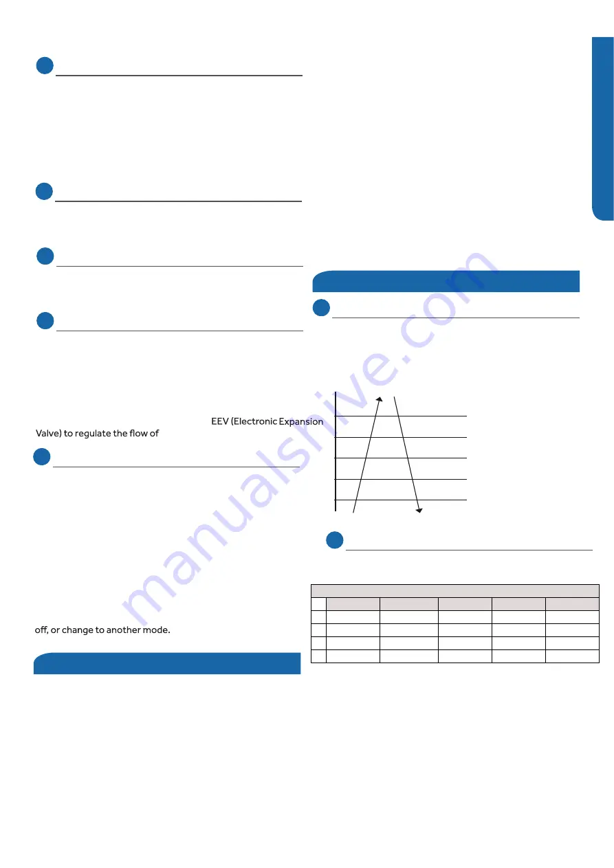
The discharge (exhaust) sensor monitors the temperature
of the refrigerant leaving the compressor. Compressor
speed will either increase, decrease, or the compressor may
stop in response to temperatures reported by the discharge
sensor. Refer to the table below.
When a call for defrost initiates, the compressor slowly ramps
down, then runs for 30 seconds at a very low speed.
1 minute from the call for defrost, the 4WV switches to cooling,
all fans stop, and the EEV changes to a mid-range. Once these
functions are completed, the compressor ramps up to a high
speed.
When the outdoor coil reaches more than 45 degrees for 60
seconds, or more than 54 degrees for 30 seconds, the defrost
cycle will terminate. The compressor then returns to a very
low speed for 1 minute while all components return to the
heating mode.
The defrost cycle is terminated automatically after 10 minutes
if the coil does not reach the specified temperatures.
Abnormal stop
Decreasing the frequency rapidly (1HZ/1sec
ond)
230
°F
212
°F
209
°F
199
°F
194
°F
Decreasing the frequency slowly (1HZ/10 sec
onds)
The frequency doesn’t change
Increasing the frequency (1HZ/10 sec
onds)
Increasing the frequency (1HZ/1sec
ond)
2. Overheating protection for indoor unit
coil sensor monitors temperature at the coil surface
according to the table below.
Overheating protection for indoor unit
Increasing slowly
Decreasing slowly Decreasing rapidly Compressor stop
Prohibiting increasing
48
℃
/118
℉
51
℃
/124
℉
56
℃
/133
℉
59
℃
/138
℉
63
℃
/145
℉
63
℃
/145
℉
63
℃
/145
℉
63
℃
/145
℉
59
℃
/138
℉
60
℃
/140
℉
60
℃
/140
℉
56
℃
/133
℉
56
℃
/133
℉
56
℃
/133
℉
51
℃
/124
℉
53
℃
/127
℉
53
℃
/127
℉
48
℃
/118
℉
48
℃
/118
℉
48
℃
/118
℉
09K
12K
18K
24K
Summary of Contents for ASYW09CRAWA
Page 2: ...This page intentionally left blank...
Page 6: ...INTRODUCTION PAGE 6...
Page 26: ...INSTALLATION PAGE 42 ENGLISH This page intentionally left blank...
Page 58: ...REFERENCE INFORMATION PAGE 58 ENGLISH Outdoor Board Schematic 9 12K...
Page 59: ...REFERENCE INFORMATION PAGE 59 Outdoor Board Schematic Outdoor Board Schematic ENGLISH...
Page 63: ...REFERENCE INFORMATION PAGE 63 ENGLISH Indoor Board Schematic 09 12K...


