Installation
ATS125x 4-door DGP overview
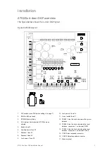
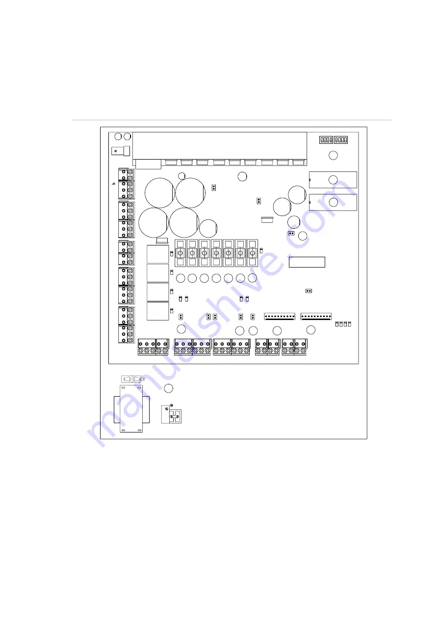
The figure below shows the 4-door DGP layout.
Figure 1: ATS125x layout
ATS125x
MODE
ADDRESS
IC13 RAM/IUM
IC6 EPROM
F1
F2
F3
F4
F5
F6
F7
K1
K2
K3
K4
J1
CON14
CON13
OUTPUT EXPANDER
INPUT EXPANDER
TxD
RT
S
Rx
D
CT
S
CON11
CON10
CON9
CON8
CON7
CON6
12V
D-
0V
D+
12V
D-
0V
D+
1
C
2
3
4
5
6
7
8
C
C
C
0V D+ D- T
C
CON1
CON2
CON3
CON4
CON5
Tx1
Rx
1
Tx
Rx
NO
COM
NC
NO
COM
NC
NO
COM
NC
NO
COM
NC
+
-
+
-
+
-
+
-
S-
S+
+
+
-
~
~
LK8
TERM3
LK7
TERM2
LK6
TERM1
LK3
TST1
LK4
TST2
LK1
PTC1
LK2
PTC2
LK11
TST3
LK10
KILL
RST
1
2
3
4
5
6
7
8
9
10
11
12
13
14
15
16
17
L
N
1.
DIP switches (see “DIP switch settings” on page 7)
2.
RAM or IUM (optional)
3. EPROM
(factory
fitted)
4.
KILL jumper: Factory default ATS125x when
shorted
5.
Battery fuse F1
6.
Auxiliary power fuse F2
7.
Databus 1 fuse F3
8.
Databus 2 fuse F4
9.
Lock power 1 fuse F5
10. Lock power 2 fuse F6
11. Siren / switch fuse F7
12. TERM 1: Use this link to terminate the system
databus
13. TERM 2: Use this link to terminate the local
databus, connection 1 on terminal CON9
14. TERM 3: Use this link to terminate the local
databus, connection 2 on terminal CON10
15. CON14 Input expander connector
16. CON15 Output expander connecter
17. Mains
terminal
ATS125x 4-Door DGP Installation Manual
1


