Cabling
System databus preferred wiring
The
TERM
link is on the first and last devices on the system databus. In a star-wiring
configuration, the TERM link is only fitted on the devices at the ends of the two
longest system databus cable runs.
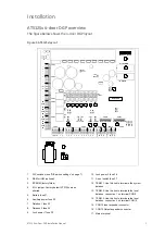
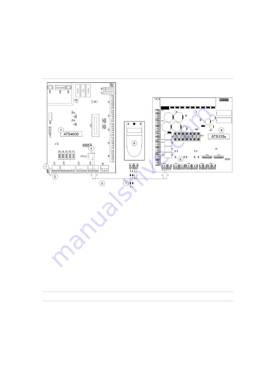
Figure 2: System databus wiring example
1.
GND link (
do not fit
).
2.
Earth lug to connect shield.
3.
ATS4000 control panel.
4.
ATS4000 TERM link fitted (first device on system
databus).
5.
Preferred data cable type is WCAT 52 (two twisted
pairs).
6.
ATS1110 LCD RAS (TERM switch
not
set to ON).
7.
Separate 12 V power supply. Required if RAS is
more than 100 m from the nearest panel or DGP.
Connect the negative terminal of the power supply
to the “
−
” wire of the databus.
8.
ATS125x TERM link fitted (last device on system
databus).
9. ATS125x
4-Door
DGP.
Note:
The local databus (not shown) has the same requirements. The local databus is
connected to CON9/CON10 of the ATS125x.
See “ATS system databus connection”, “ATS125x local databus and earth connection”,
and earthing details below.
Earthing
WARNING:
Correct earthing procedure must be followed.
Earthing of one cabinet containing several devices
All devices designed for the system allow earth connection to the metal housing via
metal studs. Take care that these metal studs have a good connection to the housing
(beware of paint).
ATS125x 4-Door DGP Installation Manual
5


