8-2
B30 BUS DIFFERENTIAL SYSTEM – INSTRUCTION MANUAL
OVERVIEW
CHAPTER 8: APPLICATION OF SETTINGS
8
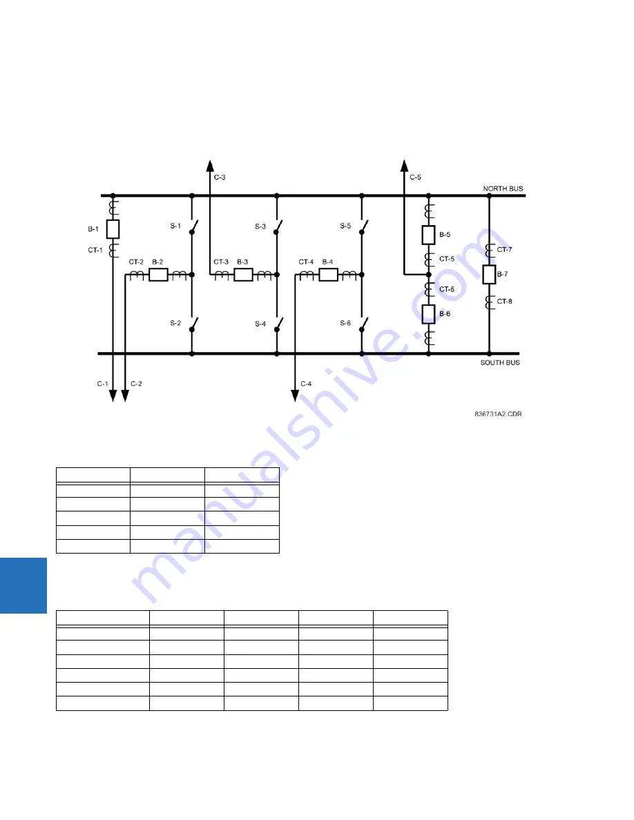
8.1.2 Sample busbar and data
The figure shows a double bus arrangement with North and South buses. This station has five circuits (C-1 through C-5)
and a tiebreaker (B-7). Circuit C-1 is connected to the North bus; circuits C-2, C-3 and C-4 can be routed to either bus via
switches S-1 through S-6; circuit C-5 can be connected to either bus via breakers B-5 and B-6.
Figure 8-1: Sample bus configuration
The table shows the assumed short circuit contributions of the connected circuits and their DC time constants.
Table 8-1: Basic fault data of the connected circuit
The basic CT data is presented in the following table. The magnetizing characteristics of the three different types of CTs
used in this example are shown in the following figure.
Table 8-2: Basic CT data
Circuit
I
FAULT
(kA)
T
DC
(ms)
C-1
0.00
N/A
C-2
0.00
N/A
C-3
6.00
5
C-4
5.00
30
C-5
3.00
40
CT
Ratio
V
sat
(V)
R
CTsec
(
Ω
)
Leads (m)
CT-1
600:5
144
0.34
210
CT-2
600:5
144
0.34
205
CT-3
1200:5
288
0.64
200
CT-4
1000:5
240
0.54
200
CT-5, CT-6
1000:5
240
0.54
180
CT-7, CT-8
1200:5
288
0.64
200
Summary of Contents for b30
Page 10: ...x B30 BUS DIFFERENTIAL SYSTEM INSTRUCTION MANUAL TABLE OF CONTENTS ...
Page 486: ...5 278 B30 BUS DIFFERENTIAL SYSTEM INSTRUCTION MANUAL TESTING CHAPTER 5 SETTINGS 5 ...
Page 616: ...iv B30 BUS DIFFERENTIAL SYSTEM INSTRUCTION MANUAL ABBREVIATIONS ...
Page 632: ...xvi B30 BUS DIFFERENTIAL SYSTEM INSTRUCTION MANUAL INDEX ...


