8-4
B30 BUS DIFFERENTIAL SYSTEM – INSTRUCTION MANUAL
ZONING AND DYNAMIC BUS REPLICA
CHAPTER 8: APPLICATION OF SETTINGS
8
•
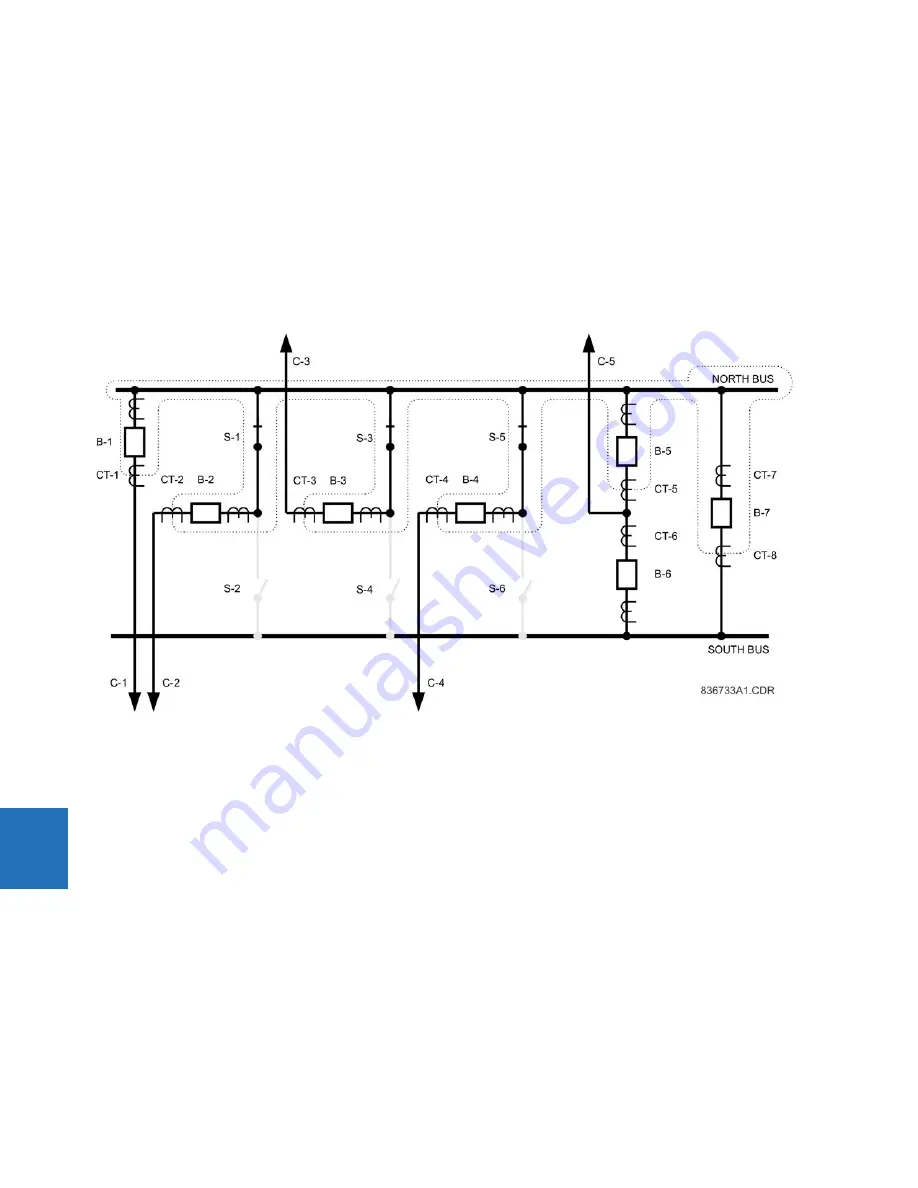
CT-5 currents are configured as SRC 5 and used as the source 1E of the bus differential zone 1 together with the
FlexLogic “On” constant for the status
•
CT-8 currents are configured as SRC 6 and used as the source 1F of the bus differential zone 1 together with the
FlexLogic “On” constant for the status
•
The trip signal are routed directly to the B-1, B-5 and B-7 breakers while it is supervised by the status of S-1, S-3 and S-
5 for the B-2, B-3 and B-4 breakers, respectively
Depending on utility practice, extra security is required with respect to the status signals. This can include bringing in both
the normally opened and normally closed contacts of a switch as well as status of a peer switch (S-1 and S-2, for example).
If this is the case, set up the required security filtering using FlexLogic and indicate a single (final) status operand for the
status signal when setting the bus differential zone.
Figure 8-3: North bus zone
8.2.3 South bus zone
The South bus differential zone is bounded by the following CTs: CT-2 (if S-2 closed), CT-3 (if S-4 closed), CT-4 (if S-6 closed),
CT-6 and CT-7. The South bus protection is to operate the following breakers: B-2 (if S-2 closed), B-3 (if S-4 closed), B-4 (if S-
6 closed), B-6 and B-7.
Consequently, the second UR for the South bus are wired and configured as follows:
•
CT-2 currents are configured as SRC 1 and used as the source 1A of the bus differential zone 1 together with the
status of the S-2 switch
•
CT-3 currents are configured as SRC 2 and used as the source 1B of the bus differential zone 1 together with the
status of the S-4 switch
•
CT-4 currents are configured as SRC 3 and used as the source 1C of the bus differential zone 1 together with the
status of the S-6 switch
•
CT-6 currents are configured as SRC 4 and used as the source 1D of the bus differential zone 1 together with the
FlexLogic “On” constant for the status
•
CT-7 currents are configured as SRC 5 and used as the source 1E of the bus differential zone 1 together with the
FlexLogic “On” constant for the status
Summary of Contents for b30
Page 10: ...x B30 BUS DIFFERENTIAL SYSTEM INSTRUCTION MANUAL TABLE OF CONTENTS ...
Page 486: ...5 278 B30 BUS DIFFERENTIAL SYSTEM INSTRUCTION MANUAL TESTING CHAPTER 5 SETTINGS 5 ...
Page 616: ...iv B30 BUS DIFFERENTIAL SYSTEM INSTRUCTION MANUAL ABBREVIATIONS ...
Page 632: ...xvi B30 BUS DIFFERENTIAL SYSTEM INSTRUCTION MANUAL INDEX ...


