3-28
B30 BUS DIFFERENTIAL SYSTEM – INSTRUCTION MANUAL
WIRING
CHAPTER 3: INSTALLATION
3
* Default debounce time on contact inputs is 6 ms.
The value of this resistor "R" is calculated as follows:
1.
Determine the minimum voltage (V threshold) required to turn on the input. This is determined by direct measurement
or referenced in the input specifications.
2.
Calculate the resistance necessary to limit the voltage to 1/3 V threshold (when the contact is OFF, the non-activated
state) as follows:
R = (Vthreshold / 3) / (2 mA)
Eq. 3-2
The 2 mA current is used in case the contact input is connected across the GE Form A contact output with voltage
monitoring. Otherwise use the amperage of the active circuit connected to the contact input when its contact output
is open and the voltage across the contact input is third trigger threshold to calculate the resistor value.
3.
When the contact is ON (operate state), the battery voltage appears across the resistor. The wattage rating of the
resistor is then:
PR = 1.3 * (Vbatt) ^2 / R Watts
Eq. 3-3
4.
Applying the following equation to our example:
R = 84 V / 3 * (1 / 2 mA) = 14 k
Ω
PR = 1.57 Watts
Eq. 3-4
5.
Calculating the voltage across the contact input with the Burden Resistor, Voltage across the contact Input:
Vresistor = 2 mA * 14 Kohm = 28 V
Vresistor < contact input threshold (84 V)
Eq. 3-5
In conclusion, in this example, the contact input does NOT operate falsely with the Burden Resistor across its input AND
when a battery ground is present.
3.3.6.3 Use of contact inputs with auto-burnishing
The contact inputs sense a change of state of the external device contact based on the measured current. When external
devices are located in a harsh industrial environment (either outdoor or indoor), their contacts can be exposed to various
types of contamination. Normally, there is a thin film of insulating sulfidation, oxidation, or contaminates on the surface of
the contacts, sometimes making it difficult or impossible to detect a change of state. This film must be removed to
establish circuit continuity — an impulse of higher than normal current can accomplish this.
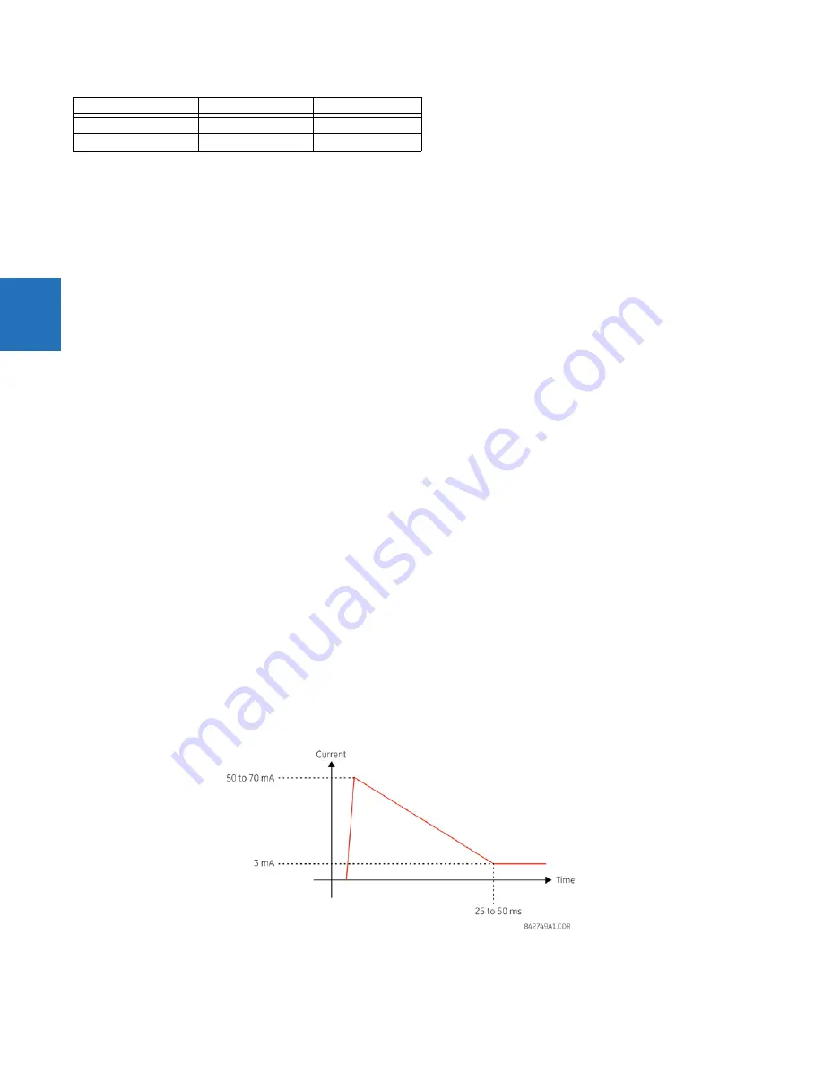
The contact inputs with auto-burnish create a high current impulse when the threshold is reached to burn off this oxidation
layer as a maintenance to the contacts. Afterwards the contact input current is reduced to a steady-state current. The
impulse has a five-second delay after a contact input changes state.
Figure 3-25: Current through contact inputs with auto-burnishing
0.1
250
6 *
0.2
250
11
Stray capacitance (
μ
F)
Battery voltage (V)
Debounce time (ms)
Summary of Contents for b30
Page 10: ...x B30 BUS DIFFERENTIAL SYSTEM INSTRUCTION MANUAL TABLE OF CONTENTS ...
Page 486: ...5 278 B30 BUS DIFFERENTIAL SYSTEM INSTRUCTION MANUAL TESTING CHAPTER 5 SETTINGS 5 ...
Page 616: ...iv B30 BUS DIFFERENTIAL SYSTEM INSTRUCTION MANUAL ABBREVIATIONS ...
Page 632: ...xvi B30 BUS DIFFERENTIAL SYSTEM INSTRUCTION MANUAL INDEX ...


