CHAPTER 3: INSTALLATION
WIRING
B30 BUS DIFFERENTIAL SYSTEM – INSTRUCTION MANUAL
3-29
3
Regular contact inputs limit current to less than 3 mA to reduce station battery burden. In contrast, contact inputs with
auto-burnishing allow currents up to 50 to 70 mA at the first instance when the change of state is sensed. Then, within 25
to 50 ms, this current is slowly reduced to 3 mA as indicated. The 50 to 70 mA peak current burns any film on the contacts,
allowing for proper sensing of state changes. If the external device contact is bouncing, the auto-burnishing starts when
external device contact bouncing is over.
Another important difference between the auto-burnishing input module and the regular input modules is that only two
contact inputs have common ground, as opposed to four contact inputs sharing one common ground (see the Contact
Input and Output Module Wiring diagrams). This is beneficial when connecting contact inputs to separate voltage sources.
Consequently, the threshold voltage setting is also defined per group of two contact inputs.
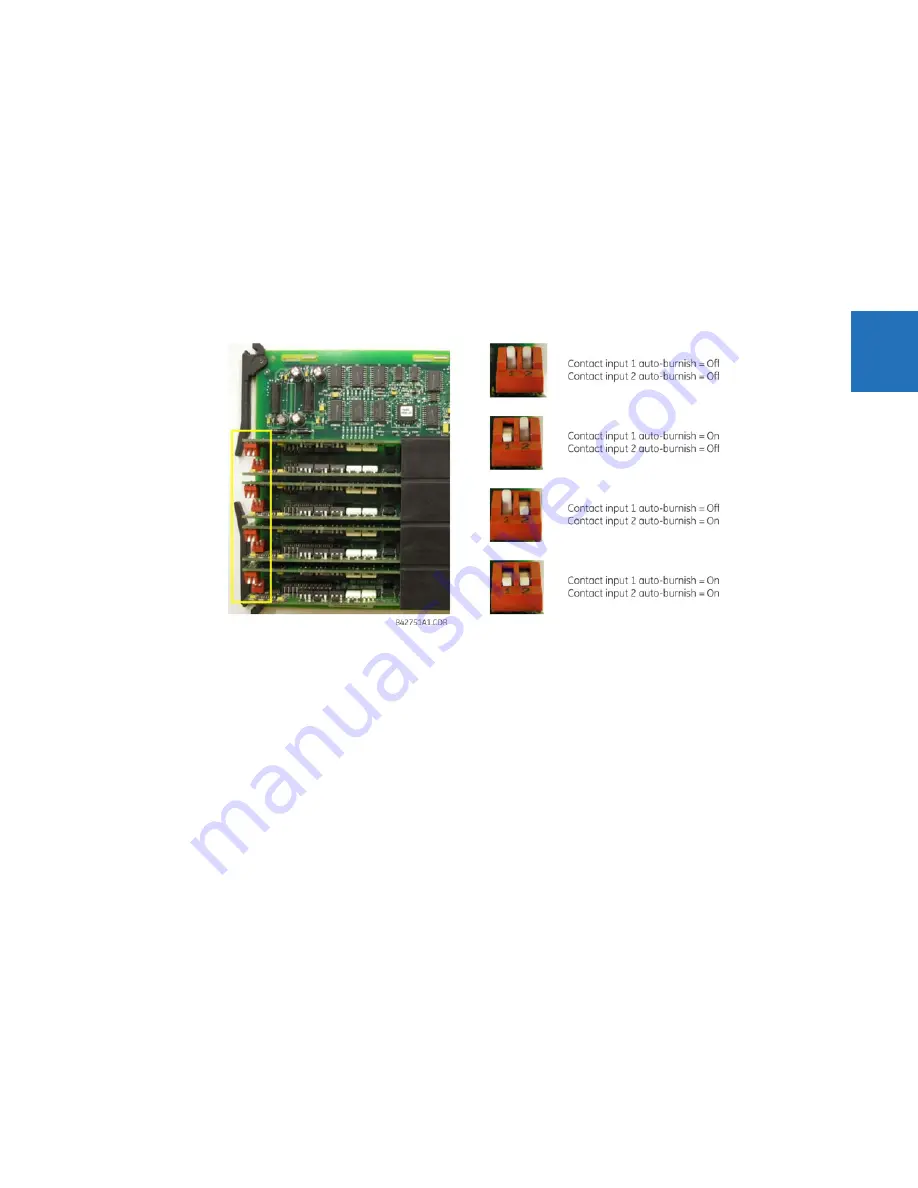
The auto-burnish feature can be disabled or enabled using the DIP switches found on each daughter card. There is a DIP
switch for each contact, for a total of 16 inputs.
Figure 3-26: Auto-burnish DIP switches
The auto-burnish circuitry has an internal fuse for safety purposes. During regular maintenance, check the auto-burnish
functionality using an oscilloscope.
3.3.6.4 Use of contact inputs with active impedance
Contact inputs can be susceptible to parasitic capacitance, caused by long cable runs affected by switching surges from
external circuits. This can result in inadvertent activation of contact inputs with the external contact open. In this case, GE
recommends using the contact I/O module with active impedance circuit.
Active impedance contact input can tolerate external cable capacitance of up to 0.2 µF, without entering the ON state for
more than 2 ms. The contact input debounce time can still be set above 2 ms for added security to prevent contact input
activations caused by external transient ON states.
An active impedance contact input is normally in Low impedance mode during OFF contact state (non-activated
condition). During Low impedance state, contact input impedance is maintained at 10 K Ohms impedance to allow fast
discharge of the stray capacitance of the long cables.
When the contact input voltage exceeds the set threshold, active impedance maintains 10 K Ohms impedance. If voltage
starts rapidly decreasing, this indicates that stray capacitance is being discharged through the contact input. If, however,
voltage stabilizes above the set threshold, the input impedance is switched to High impedance mode of 100 K Ohms. This
value reduces the input current to <3 mA, and contact input switches to the ON state (operated state).
The figure shows the active impedance contact input V-I characteristic. Different thresholds with their corresponding
characteristics are shown by color. The contact input is in the ON (operated) state if the input voltage is to the right of the
colored threshold band (+/-10% tolerance), and the contact input is in the OFF (non-activated) state when input voltage is
to the left of the band. A contact input is in LOW state during non-operated system condition, and actively switches to
HIGH state upon detection of input voltage above the settable threshold.
Summary of Contents for b30
Page 10: ...x B30 BUS DIFFERENTIAL SYSTEM INSTRUCTION MANUAL TABLE OF CONTENTS ...
Page 486: ...5 278 B30 BUS DIFFERENTIAL SYSTEM INSTRUCTION MANUAL TESTING CHAPTER 5 SETTINGS 5 ...
Page 616: ...iv B30 BUS DIFFERENTIAL SYSTEM INSTRUCTION MANUAL ABBREVIATIONS ...
Page 632: ...xvi B30 BUS DIFFERENTIAL SYSTEM INSTRUCTION MANUAL INDEX ...


