© 2019 Baker Hughes, a GE company, LLC. All rights reserved.
32
|
BHGE
Step 3: Wire the SVI FF
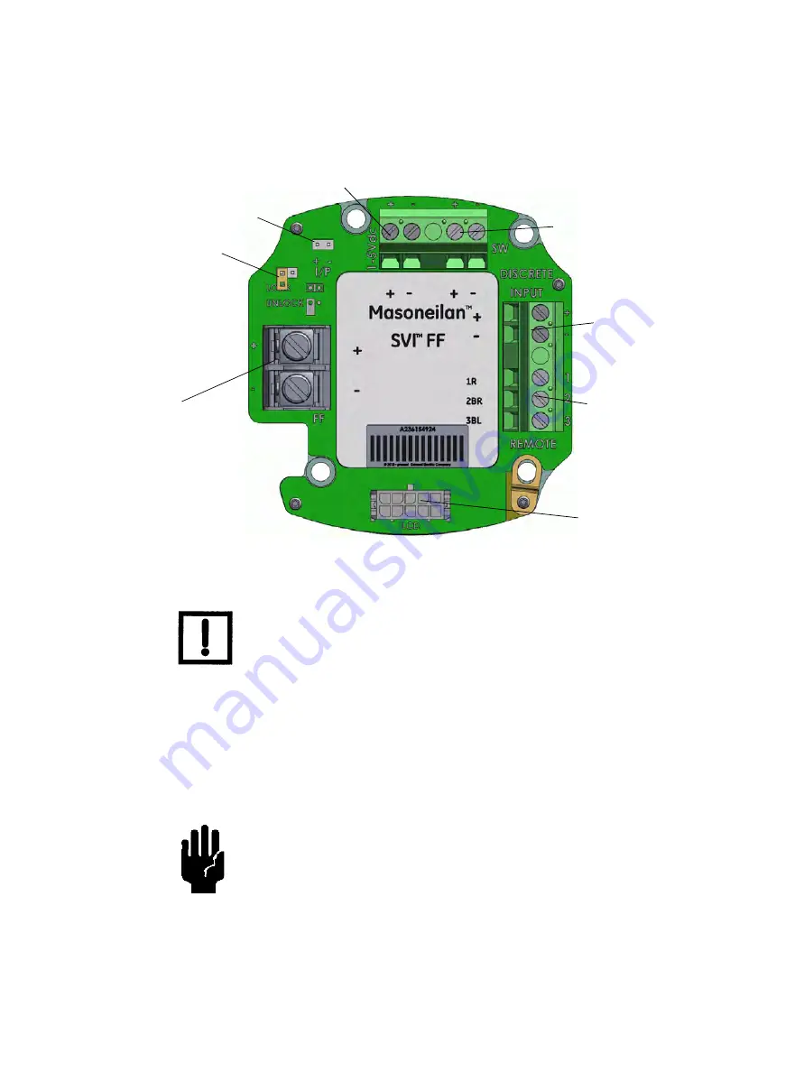
Perform wiring as per Figure 8.
Figure 8 Connections to Electronics Module (via Terminal Board)
Step 4: Set Tag and Address
Using NI Configurator as an example:
1. Import DD/CFF files.
2. Right-click on the device, select
Set Tag
, follow the prompts to enter a
Tag.
3. Click
Set
.
Refer to FOUNDATION Fieldbus instructions for shield connections
on the FF H1 bus.
Do not navigate to the NI DD folder and copy the DD file onto itself.
Display
Remote
I/P Connector
Position
Sensor
Configuration Lock
Jumper
9 - 32 V
Foundation Fieldbus
Discrete Out
Input
Discrete Input
AI PV 1-5 VDC (Not Used in this release)
Shield
(on FF unit
Input Signal
(polarity independent)
housing)
NOTE
CAUTION
Summary of Contents for Baker Hughes Masoneilan SVI FF
Page 12: ...This page intentionally left blank ...
Page 72: ...This page intentionally left blank ...
Page 82: ...This page intentionally left blank ...
Page 94: ...This page intentionally left blank ...
Page 108: ...This page intentionally left blank ...
Page 198: ...This page intentionally left blank ...
Page 206: ...This page intentionally left blank ...
Page 224: ...This page intentionally left blank ...
Page 228: ...This page intentionally left blank ...
Page 230: ...This page intentionally left blank ...
Page 250: ...This page intentionally left blank ...
Page 262: ...This page intentionally left blank ...
Page 263: ......


