13 | GE Oil & Gas
© 2014 General Electric Company. All rights reserved.
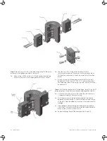
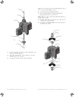
Step 3� Place O-ring -011 (X1) in the adjusting orifice (W)� Place the
assembly in the gauge manifold (V) as shown�
3a� Place O-ring -011(X1) in the nuts (X) and secure the adjusting
orifice (W) with nuts (X) in the gauge manifold (V) as shown�
3b� Seat the four –012 O-rings (L) and roll pins (M) into
the inlet and exhaust port recesses on the pilot body block
(F)� (Note the orientation of the body in relation to the orifice
block)�
3c� Attach orifice block (K) and gauge manifold (N) to the pilot
body block (F) with four 1/4 - 20 x 2 1/2-inch stainless steel
hex head cap screws (J) by lining it up with roll pins (M) in pilot
body block (F)
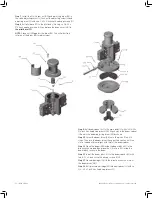
Step 4. Test the pilot body block (F) for leakage� Using 1/4-inch NPT
plugs, plug the orifice block ports (K) and the gauge manifold (N)�
4a� Connect a pressure source to the orifice block (K) as shown�
Use approximately 100 psig for testing�
4b� With the pressure source activated, soap test around the
balanced valve assembly (C) on both the bottom and the top
of the pilot� Place a bubble on the exhaust port and check for
leakage�
4c� If any leakage is detected, repeat the assembly procedure
from Step 1� (vertical cross hole must be blocked with plastic
plugs in order to check exhaust port)�
4d� Remove all plugs from all blocks/manifolds [K and N]�
Summary of Contents for Becker HPP-5
Page 18: ... ...


