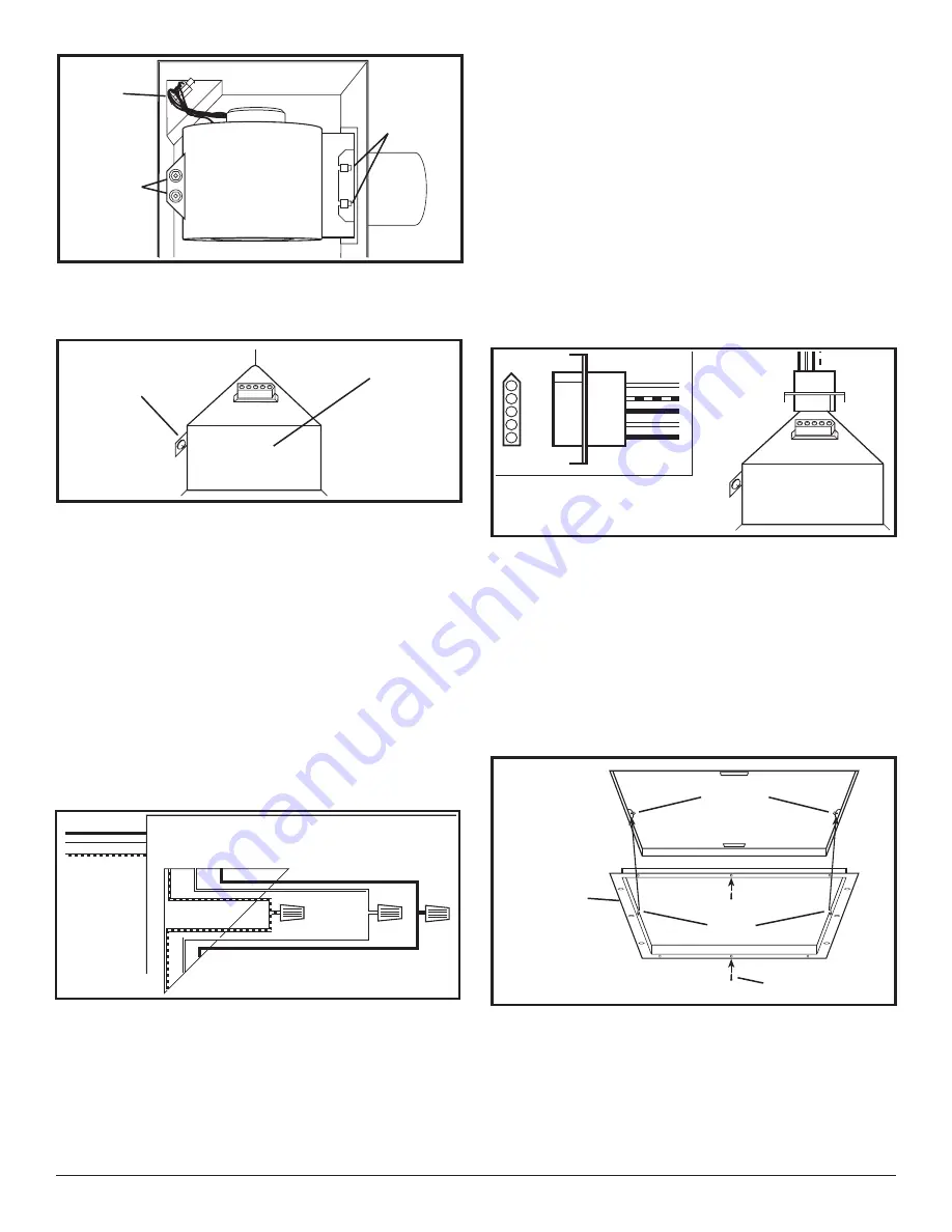
background image

Figure 8

Plug

Hex Nuts

Tabs

Figure 11

210572117 Rev. B 5-06

NOTE:

 If the fan motor plug is connected to the fan

housing receptacle, unplug so the blower assembly can
be completely removed.

2. Run wiring from an approved wall switch carrying the

appropriate rating. One neutral (white), one ground
(green or bare copper), and one hot (black lead
connected to the switch). Secure the electrical wires
to the housing with an approved electrical connector.
Make sure you leave enough wiring in the box to make
the connection to the fan’s receptacle.

3. From where you have chosen to access the fan’s

junction box, connect the white wire from the house
to the white wire from the fan’s receptacle. Connect
the black wire from the wall switch to the black wire
from the fan’s receptacle. Connect the ground wire
from the house to the green wire from the fan housing

(Figure 10)

. Use approved methods for all connections.

NOTE:

 The fan’s receptacle wires might need to be pulled

outside compartment for connection. Only pull the three
loose wires outside of compartment. Additional wires
will be present.

Screw

Wire Compartment

Cover

Figure 9

4. Carefully tuck wire back inside wire compartment

and replace wire compartment cover securing with
the screw that was removed earlier.

SECTION 5

Completing the Installation

1. If the fan’s blower assembly was removed during

the wiring process, reinstall the blower by reversing
the directions in 

Section 4

 (Wiring)

, Step 1b.

2. Plug the fan’s quick connect motor cord into the

receptacle. This cord will only fit one way into the
receptacle 

(Figure 11)

.

3. Install the ceiling mounting flange to cover any gaps

which exist between the housing and the finished
ceiling. Line up the slots in the ceiling mounting
flange with the screws on the inside of the housing
and press flange in place so it is tight against the
ceiling. Tighten both screws inside the housing.
Install drywall screws (not included) through the
holes in the flange and into the ceiling. Install as
many drywall screws needed to ensure the flange
fits tightly against the ceiling 

(Figure 12)

.

4. Install the grill by squeezing the two ends of the

springs together and installing them up into the slots
on the fan’s housing. Push the grill up into position

(Figure 13)

.

Ground

Hot (Black)

White

Supply from

house

Figure 10

Figure 12

Drywall Screw

Ceiling
Mounting
Flange

Slots

Screws

4 of 8

www.geelectrical.com

Summary of Contents for BF230UQ

Page 1: ...he following 1 Read all instructions before installing or using exhaust fan 2 Use this unit only in the manner intended by the manufacturer If you have questions contact the manufacturer 3 Before servicing or cleaning the unit switch power off at service panel and lock the service disconnecting means to prevent power from being switched on SAVE THESE INSTRUCTIONS IMPORTANT INSTRUCTIONS OPERATING M...

Page 2: ... the location for your fan To ensure the best air and sound performance it is recommended that the length of ducting and the number of elbows be kept to a minimum and that insulated hard ducting be used Larger duct sizes will reduce noise and airflow restrictions This fan will require at least 10 of clearance in the ceiling or wall and will mount through drywall up to 3 4 thick 3 Select the most c...

Page 3: ...HED OFF AT SERVICE PANEL BEFORE STARTING INSTALLATION CAUTION ALLELECTRICALCONNECTIONSMUST BE MADE IN ACCORDANCE WITH LOCAL CODES ORDINANCES OR NATIONAL ELECTRICAL CODE IF YOU ARE UNFAMILIAR WITH METHODS OF INSTALLING ELECTRICAL WIRING SECURE THE SERVICES OF A QUALIFIED ELECTRICIAN NOTE This unit includes a side access panel for wiring that does not require the removal of the fan s blower assembly...

Page 4: ...e Compartment Cover Figure 9 4 Carefully tuck wire back inside wire compartment and replace wire compartment cover securing with the screw that was removed earlier SECTION 5 Completing the Installation 1 If the fan s blower assembly was removed during the wiring process reinstall the blower by reversing the directions in Section 4 Wiring Step 1b 2 Plug the fan s quick connect motor cord into the r...

Page 5: ...he outside 3 Fan is operating louder than normal 3a Motor is loose 3a Turn off power to unit Remove grill and check that all screws are fully tightened Restore power to unit 3b Fan blade is hitting housing of unit 3b Call your dealer for service Figure 13 210572117 Rev B 5 06 5 Restore power and test your installation SECTION 6 Use and Care CAUTION MAKE SURE POWER IS SWITCHED OFF AT SERVICE PANEL ...

Page 6: ...installer You are responsible for providing adequate electrical exhausting and other connecting facilities See the Installation Instructions provided with this product for electrical exhaust and connection details Replacement of house fuses or resetting of circuit breakers Failure of the product if it is used for something other than the intended purpose of manufacturer or used commercially Damage...

Page 7: ... 2 3 3 4 5 6 7 8 9 10 11 12 13 14 15 16 17 18 19 20 21 22 23 24 25 26 27 24 28 29 24 REPLACEMENT PARTS DIAGRAM Qty Description Replacement Part 17 1 Nut 5S2202014 18 1 Motor 210 CFM 5S2202024 1 Motor 310 CFM 5S2202025 19 1 Motor Plate 5S2202020 20 3 Screw 5S2202027 21 5 Screw 5S2202017 22 1 Motor Cap Harness AK200LS 5S2202010 1 Motor Cap Harness AK300LS 5S1202051 23 1 Internal Wire Cover 210 CFM 5...

Page 8: ...210572117 Rev B 5 06 8 of 8 ...

Reviews: