background image

Troubleshooting Guide

Trouble

Probable Cause

Suggested Remedy

1. Fan does not operate when the switch is on.

1a. A fuse may be blown or a circuit tripped.

1a. Replace fuse or reset circuit breaker.

1b. Connector plug from motor is not plugged in.

1b. Turn off power to unit. Remove Grill and plug motor into

receptacle in housing. Restore power to unit.

1c. Wiring is not connected properly.

1c. Turn off power to unit. Check that all wires are connected.

2. Fan is operating, but air moves slower than normal.

2.

Obstruction in the exhaust ducting.

2.

Check for any obstructions in the ducting. The most common
are bird nests in the roof cap or wall cap where the fan
exhausts to the outside.

3. Fan is operating louder than normal.

3a. Motor is loose.

3a. Turn off power to unit. Remove grill and check that all screws

are fully tightened. Restore power to unit.

3b. Fan blade is hitting housing of unit.

3b. Call your dealer for service.
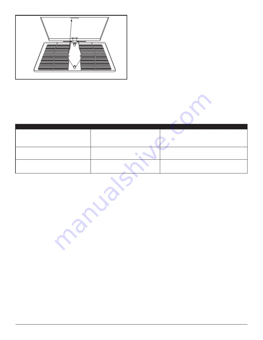
Figure 13

210572117 Rev. B 5-06

5. Restore power and test your installation.

SECTION 6

Use and Care

CAUTION:


MAKE SURE POWER IS SWITCHED

OFF AT SERVICE PANEL BEFORE SERVICING THE UNIT.

1.

Cleaning the Grill:

 Remove grill and use a mild

detergent, such as dishwashing liquid, and dry with
a soft cloth. NEVER USE ANY ABRASIVE PADS OR
SCOURING POWDERS. Completely dry grill before
reinstalling. Refer to instructions in 

Section 5

Finishing the Installation, to reinstall grill.

2.

Cleaning the Fan Assembly:

 Wipe all parts with a

dry cloth or gently vacuum the fan. NEVER IMMERSE
ELECTRICAL PARTS IN WATER.

5 of 8

www.geelectrical.com

Summary of Contents for BF230UQ

Page 1: ...he following 1 Read all instructions before installing or using exhaust fan 2 Use this unit only in the manner intended by the manufacturer If you have questions contact the manufacturer 3 Before servicing or cleaning the unit switch power off at service panel and lock the service disconnecting means to prevent power from being switched on SAVE THESE INSTRUCTIONS IMPORTANT INSTRUCTIONS OPERATING M...

Page 2: ... the location for your fan To ensure the best air and sound performance it is recommended that the length of ducting and the number of elbows be kept to a minimum and that insulated hard ducting be used Larger duct sizes will reduce noise and airflow restrictions This fan will require at least 10 of clearance in the ceiling or wall and will mount through drywall up to 3 4 thick 3 Select the most c...

Page 3: ...HED OFF AT SERVICE PANEL BEFORE STARTING INSTALLATION CAUTION ALLELECTRICALCONNECTIONSMUST BE MADE IN ACCORDANCE WITH LOCAL CODES ORDINANCES OR NATIONAL ELECTRICAL CODE IF YOU ARE UNFAMILIAR WITH METHODS OF INSTALLING ELECTRICAL WIRING SECURE THE SERVICES OF A QUALIFIED ELECTRICIAN NOTE This unit includes a side access panel for wiring that does not require the removal of the fan s blower assembly...

Page 4: ...e Compartment Cover Figure 9 4 Carefully tuck wire back inside wire compartment and replace wire compartment cover securing with the screw that was removed earlier SECTION 5 Completing the Installation 1 If the fan s blower assembly was removed during the wiring process reinstall the blower by reversing the directions in Section 4 Wiring Step 1b 2 Plug the fan s quick connect motor cord into the r...

Page 5: ...he outside 3 Fan is operating louder than normal 3a Motor is loose 3a Turn off power to unit Remove grill and check that all screws are fully tightened Restore power to unit 3b Fan blade is hitting housing of unit 3b Call your dealer for service Figure 13 210572117 Rev B 5 06 5 Restore power and test your installation SECTION 6 Use and Care CAUTION MAKE SURE POWER IS SWITCHED OFF AT SERVICE PANEL ...

Page 6: ...installer You are responsible for providing adequate electrical exhausting and other connecting facilities See the Installation Instructions provided with this product for electrical exhaust and connection details Replacement of house fuses or resetting of circuit breakers Failure of the product if it is used for something other than the intended purpose of manufacturer or used commercially Damage...

Page 7: ... 2 3 3 4 5 6 7 8 9 10 11 12 13 14 15 16 17 18 19 20 21 22 23 24 25 26 27 24 28 29 24 REPLACEMENT PARTS DIAGRAM Qty Description Replacement Part 17 1 Nut 5S2202014 18 1 Motor 210 CFM 5S2202024 1 Motor 310 CFM 5S2202025 19 1 Motor Plate 5S2202020 20 3 Screw 5S2202027 21 5 Screw 5S2202017 22 1 Motor Cap Harness AK200LS 5S2202010 1 Motor Cap Harness AK300LS 5S1202051 23 1 Internal Wire Cover 210 CFM 5...

Page 8: ...210572117 Rev B 5 06 8 of 8 ...

Reviews: