background image

210572107 Rev. C 1-08

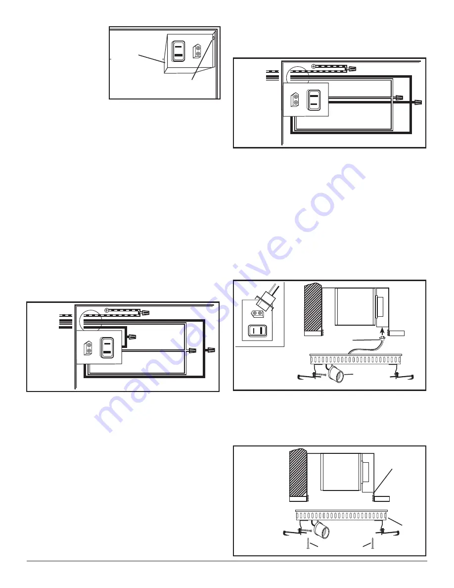
NOTE:

 If the fan

motor plug is
connected to the fan
housing receptacle,
unplug so the blower
assembly can be
completely removed.

2a.

Wiring Fan/Light Independently:

 Run wiring from an

approved wall switch carrying the appropriate rating.
One neutral (white), one ground (green or bare
copper), and two hot (black lead connected to the
switch). Secure the electrical wires to the housing
with an approved electrical connector. Make sure
you leave enough wiring in the box to make the
connection to the fan’s receptacle.

2b. From where you have access to inside the fan’s

junction box, connect the one white wire from the
house to both the white wire from the fan’s light
receptacle and the white wire from the fan’s exhaust
receptacle. Connect the first black wire from the
wall switch to the red wire from the fan’s light
receptacle. Connect the second black wire from the
house to the fan’s exhaust receptacle. Connect the
ground wire from the house to the green wire from
the fan’s grounding screw 

(Figure 9)

. Use approved

methods for all connections.

3a.

Wiring Fan/Light together:

 Run wiring from an

approved wall switch carrying the appropriate rating.
One neutral (white), one ground (green or bare 
copper), and one hot (black lead connected to the
switch). Secure the electrical wires to the housing
w ith an approved electrical connector. Make sure
you leave enough wiring in the box to make the
connection to the fan’s receptacle.

3b. From where you have access to inside the fan’s

junction box, connect the one white wire from the
house to both the white wire from the fan’s light
receptacle and the white wire from the fan’s exhaust
receptacle. Connect the black wire from the wall
switch to both the red wire from the fan’s light
receptacle and the black wire from the fan’s exhaust

receptacle. Connect the ground wire from the house
to the green wire from the fan’s grounding screw
(

Figure 10)

. Use approved methods for all connections.

4. Carefully tuck wire back inside wire compartment

and replace wire compartment cover securing with
the screw that was removed earlier.

SECTION 6

Completing the Installation

1. If the fan’s blower assembly was removed during

the wiring process, reinstall the blower by reversing
the directions in 

Step 1b in 

Section 5


Wiring.

2. Insert the fan’s plug into the receptacle (

Figure 7)

.

3. Plug cord from lamp holder into the appropriate

receptacle 

(Figure 11)

.

4. Line up slots in the grill with lances on inside of

housing. Insert included #8 screws through grill slots
and into housing lances. Tighten both screws until
the grill fits snugly to the ceiling. DO NOT OVER
TIGHTEN (

Figure 12)

.

4 of 8

Figure 8

Screw

Wire
Compartment
Cover

www.geelectrical.com

Figure 9

Ground

Hot (Red)

Supply

from

house

White

Hot
(Black)

Figure 10

Ground

Hot (Red)

Supply

from

house

White

Figure 11

Cord

Lamp
Holder

Grill

Lances

#8 Screws

Figure 12

Summary of Contents for BFL85ADW

Page 1: ...Read all instructions before installing or using exhaust fan 2 Use this unit only in the manner intended by the manufacturer If you have questions contact the manufacturer 3 Before servicing or cleaning the unit switch power off at service panel and lock the service disconnecting means to prevent power from being switched on SAVE THESE INSTRUCTIONS IMPORTANT INSTRUCTIONS OPERATING MANUAL accidenta...

Page 2: ...mper Assembly attached 2 8 Screws 2 Lockwashers 4 Mounting Rails 1 Instruction Safety Sheet 2 Choose the location for your fan To ensure the best air and sound performance it is recommended that the length of ducting and the number of elbows be kept to a minimum and that insulated hard ducting be used Larger duct sizes will reduce noise and airflow restrictions This fan will require at least 6 of ...

Page 3: ...er detaches from unit reattach by snapping the collar back onto the unit It is designed to only fit one way SECTION 5 Wiring CAUTION MAKE SURE POWER IS SWITCHED OFF AT SERVICE PANEL BEFORE STARTING INSTALLATION CAUTION ALL ELECTRICAL CONNECTIONS MUST BE MADE IN ACCORDANCE WITH LOCAL CODES ORDINANCES OR NATIONAL ELECTRICAL CODE IF YOU ARE UNFAMILIAR WITH METHODS OF INSTALLING ELECTRICAL WIRING SECU...

Page 4: ...electrical connector Make sure you leave enough wiring in the box to make the connection to the fan s receptacle 3b From where you have access to inside the fan s junction box connect the one white wire from the house to both the white wire from the fan s light receptacle and the white wire from the fan s exhaust receptacle Connect the black wire from the wall switch to both the red wire from the ...

Page 5: ...IVE PADS OR SCOURING POWDERS Completely dry all parts before reinstalling Refer to instructions in Section 6 Completing the Installation to reinstall grill and glass light lens 2 Cleaning the Fan Assembly Wipe all parts with a dry cloth or gently vacuum the fan NEVER IMMERSE ELECTRICAL PARTS IN WATER CAUTION ALLOW BULB TO COOL BEFORE REPLACING 3 Changing the Light Bulb Disconnect power to the unit...

Page 6: ...llation problem contact your dealer or installer You are responsible for providing adequate electrical exhausting and other connecting facilities See the Installation Instructions provided with this product for electrical exhaust and connection details Replacement of house fuses or resetting of circuit breakers Failure of the product if it is used for something other than the intended purpose of m...

Page 7: ... Cover 5S2234001 7 1 8 B Screw 5S1299007 8 2 6 B Screw 5S1999010 9 1 Polarized Connector 5S1299008 10 1 Receptacle 5S1999001 1 14 2 3 5 6 7 15 13 12 Qty Description Replacement Part 11 1 Motor 5S2234002 12 3 Motor Mounting Screw 5S2234003 13 1 Blower Wheel 5S2234004 14 1 Cap Screw 5S2234005 15 1 Blower Housing 5S2234006 16 1 10 B Screw 5S1299009 17 1 Base 5S5234001 18 1 Mounting Screw 5S5204004 19...

Page 8: ...210572107 Rev C 1 08 8 of 8 www geelectrical com ...

Reviews: