background image

5.4

Column packing

Introduction

This section describes how to pack media slurry in the column after the column and
hydraulic chamber have been primed.

Packing BioProcess LPLC and
MPLC columns with media slurry

It is recommended that column filling is performed immediately prior to the
column packing step. This will avoid the settlement of media, which may
negatively affect column performance.

Tip:

NOTICE

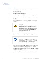
Make sure the hydraulic chamber has been primed before begin-
ning to pack the media.

For more information about priming the hydraulic chamber see Section 5.2
Priming the column, on page 52.

Note:

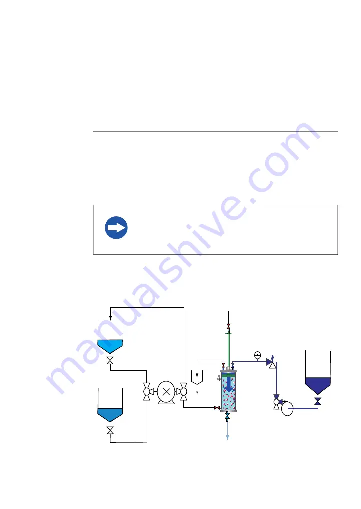
To pack a column with media slurry, follow the steps described below:

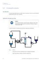
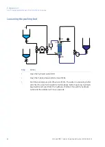
MPT

C

B

D

A

BSV

HI

HO

MPB

LPLC and MPLC Columns Operating Instructions 28-9638-66 AC

57

5 Operation

5.4 Column packing

Summary of Contents for BioProcess LPLC

Page 1: ...GE Healthcare Life Sciences BioProcess LPLC and BioProcess MPLC Columns Operating Instructions Original instructions ...

Page 2: ......

Page 3: ...f BioProcess LPLC and MPLC columns 47 4 4 2 Connecting a compressed air supply 48 4 4 3 Process connections 49 5 Operation 50 5 1 Overview of the operation of BioProcess LPLC and MPLC columns 52 5 2 Priming the column 55 5 3 Slurry preparation and column filling 57 5 4 Column packing 60 5 5 Connecting a packed column 63 5 6 Unpacking BioProcess LPLC and MPLC columns 68 6 Maintenance 71 6 1 Disasse...
Page 4: ......

Page 5: ...se of BioProcess LPLC and MPLC columns and lists of asso ciated documentation In this chapter This chapter includes the following sections See page Section 6 1 1 About this manual 7 1 2 Important user information 10 1 3 Regulatory information 13 1 4 Associated documentation LPLC and MPLC Columns Operating Instructions 28 9638 66 AC 5 1 Introduction ...

Page 6: ...c configuration information for your column can be found in the product specific documentation package and on the column label Detailed information regarding process systems media and buffer tanks is not covered Typographical conventions Software items are identified in the text by bold italic text A colon separates menu levels thus File Open refers to the Open command in the File menu Hardware it...

Page 7: ... BioProcess LPLC and MPLC columns are intended to operate at specified pressures gauge pressure of 0 to 10 bar g for LPLC columns and up to between 20 to 30 bar de pending on the specific MPLC column please refer to the Equipment Data Sheet EDS inthecolumndocumentationprovidedforindividualcolumnspecifications Consequently local authorities may consider BioProcess LPLC and MPLC columns to be pressu...

Page 8: ...uct See definitions below EX WARNING EXPLOSION HAZARD The triangle EX warning symbol highlights instructions that must be followed to avoid death or serious injury when working in a potentially explosive environment It is important not to proceed until all stated conditions are met and clearly under stood Warnings WARNING WARNING indicates a hazardous situation which if not avoided could result in...

Page 9: ...ICE NOTICE indicates instructions that must be followed to avoid damage to the product or other equipment LPLC and MPLC Columns Operating Instructions 28 9638 66 AC 9 1 Introduction 1 2 Important user information ...

Page 10: ...See EC Declaration of Conformity Place and date of declaration See EC Declaration of Conformity Identity of person authorized to sign DoC International standards The standard requirements fulfilled by this product are summarized in the table below Notes Description Standard Harmonized with 2006 42 EC Safety of machinery General princi ples for design Risk assessment and risk reduction EN ISO 12100...

Page 11: ...D 1 1997 23 EC ATEX Directive2 1994 9 EC CE Marking The CE marking and the corresponding Declaration of conformity is valid for the instrument when it is used as a stand alone unit or connected to other CE marked instruments or connected to other products recommended or described in the user documentation and used in the same state as it was delivered from GE Healthcare except for alterations desc...

Page 12: ...oProcess LPLC or MPLC columns should meet the safety requirements of EN 61010 1 IEC 61010 1 or relevant harmonized standards Within EU connected equipment must be CE marked 12 LPLC and MPLC Columns Operating Instructions 28 9638 66 AC 1 Introduction 1 3 Regulatory information ...

Page 13: ... entire process flow all components and instruments and the control system P ID Piping and Instrument Diagram Technical data for the column EDS Equipment Data Sheet Physical layout Provides all dimensional data AD Assembly Drawing Detailed specifications for process related components EQL Equipment List EC declaration of conformity DoC Declaration of Conformity1 List of spare parts available from ...

Page 14: ...g BioProcess LPLC or MPLC columns all users must read and understand the entire contents of this chapter to become aware of the hazards involved Failure to do this may cause human injury or death or damage to the equipment In this chapter This chapter contains the following sections See page Section 15 2 1 Safety precautions 26 2 2 Labels 29 2 3 Emergency procedures 30 2 4 Recycling information 14...

Page 15: ...olumns WARNING Do not operate BioProcess LPLC or MPLC columns in any other way than described in the BioProcess LPLC and MPLC column instruction manual WARNING The customer must ensure that all installation maintenance operation and inspection is carried out by qualified personnel who are adequately trained understand and adhere to local regulations and the operating instructions and have a thorou...

Page 16: ...the use of the BioProcess column and processes have on the classification of the hazardous area The process might cause the area to increase or the zone classification to change Implement the risk reduction measures needed including use of personal protection equipment WARNING High pressure The emergency shutdown might result in high pressures in the column and connected equipment flow path NOTICE...

Page 17: ... columns consult local authorities regarding local rules and regulations before installing or operating EX WARNING EXPLOSION HAZARD EX classification of BioProcess LPLC and MPLC columns is valid only when it is used according to the EX related safety instructions in this and the sub sequent chapters The information is suggested best working practice but shall not take precedence over individual re...

Page 18: ...col umn Prepare procedures for handling leakages and testing after corrective actions Risk of air entering the flow path during filling and emptying the column which might create an explosive atmosphere when being mixed with vaporized solvent Make sure that the liquid flow path always is filled with 20 ethanol between runs Risk of smaller leakages during maintenance Make sure there are no active i...

Page 19: ...OSION HAZARD Avoid discharge from static electricity when working in potentially explosive atmospheres by Always using suitable clothing Making sure that the entire system including the frame piping and column are connected to the plant grounding network Use only non sparking tools rated for EX work EX WARNING EXPLOSION HAZARD Only tools and equipment for use in potentially explosive atmo spheres ...

Page 20: ...ing it with solvents EX WARNING EXPLOSION HAZARD When preparing organic solvent based buffers in an empty container always first fill the container with inert gas Work quickly with open containers Otherwise oxygen and organic solvents might mix and create a potentially explosive atmosphere EX WARNING Before maintenance or if the column is to be moved to a non EX rated area make sure that any flamm...

Page 21: ...ance of BioProcess LPLC or MPLC columns WARNING High pressure BioProcess LPLC and MPLC columns operate under high pressure Wear protective glasses and other required Personal Protective Equipment PPE at all times Installing and moving WARNING Only personnel with appropriate training may move and unpack the delivery crates All movements and unpacking must be performed in adherence with local regula...

Page 22: ...AUTION Installing and moving the equipment involves lifting heavy parts It is advisable to always have at least two people on hand as well as a hoist when moving or lifting BioProcess LPLC or MPLC columns Operation WARNING Before use check that the column is not damaged or otherwise defective Damaged or defective columns might leak or rupture WARNING High pressure The flow rate may under no circum...

Page 23: ...sconnecting WARNING Do not reset after an emergency shutdown if the column or piping is suspected to be damaged or otherwise defective Damaged or defective columns or piping might leak or rupture WARNING Ensure that any tubing on the floor is placed so that the risk for tripping accidents is minimized CAUTION Do not touch the column while pumping fluid that has a temperature above the normal worki...

Page 24: ...column cannot become accidentally re energized refilled or re contaminated during maintenance clear LOTO tagging is applied WARNING Only spare parts and accessories that are approved or supplied by GE Healthcare may be used for maintaining or servicing the column WARNING Do not perform any type of maintenance work on the column while the adapter is in motion Do not reach inside the column while mo...

Page 25: ...pment may involve lifting heavy parts It is advisable to always have at least two people on hand as well asahoist whenperformingserviceandmaintenanceonBioProcess LPLC or MPLC columns NOTICE Do not use chemicals other than those proven not harmful to the wetted parts of the column LPLC and MPLC Columns Operating Instructions 28 9638 66 AC 25 2 Safety instructions 2 1 Safety precautions ...

Page 26: ...he identification label found on BioProcess LPLC and MPLC columns The label shows the specific manufacturing and performance data for individual BioProcess LPLC or MPLC columns II 3G T6 Explaination of the information that may be shown on the label is provided in the following table 26 LPLC and MPLC Columns Operating Instructions 28 9638 66 AC 2 Safety instructions 2 2 Labels ...

Page 27: ...rial No GE Healthcare Model No Year of Manufacture Operating Temperature TS Design pressure PS Test Pressure PT Tare mass Maximum filling mass Maximum column volume V Ex II 3G T6 Number indicatinginstrument is a BioProcess LPLC or MPLC column product Code No Number of the specific column Serial No Number indicating the specific type of column Model No Year the column was produced Year of manufactu...

Page 28: ... Section 2 3 Emergency procedures on page 29 for further information regarding the emergency stop IMPORTANT Before service maintenance or return to GE Healthcare clean the equipment and accompany it with a decontamination statement specifying substances with which it has been in contact during use and the method of cleaning CAUTION Do not use any solvent solution when cleaning transparent plastic ...

Page 29: ...example if a leak is suspected or detected perform the following action to stop the run Action Step Push the Emergency Stop button on the control panel of the BioProcess system connected to the BioProcess LPLC or MPLC column This will shut down the chromatography system coupled to the column and stop the flow of fluid to the BioProcess LPLC or MPLC column 1 Release the pressure in the column and c...

Page 30: ... decommissioning and all local regulations shall be followed with regard to scrapping of the equipment Disposal general instructions When taking BioProcess LPLC or MPLC columns out of service the different materials must be separated and recycled according to national and local environmental regula tions 30 LPLC and MPLC Columns Operating Instructions 28 9638 66 AC 2 Safety instructions 2 4 Recycl...

Page 31: ... specially designed flow distribution system fitted at the top and bottom of the column that ensures a uniform distribution of the mobile phase across the whole bed An adapter in the form of a piston is used to regulate the bed height The column the adapter and other wetted parts may be constructed of a Hastelloy alloy or stainless steel Illustration A columnand control box LPLC and MPLC Columns O...

Page 32: ...om column to column For specific configuration details refer to the product documentation package provided with your BioProcess LPLC or MPLC column 1 2 3 4 5 11 12 10 8 7 6 9 Description Part Safety valve 1 Bypass valve 2 Pressure gauge 3 Manual slurry valve 4 Pneumatic slurry valve 5 Mobile phase top valve 6 32 LPLC and MPLC Columns Operating Instructions 28 9638 66 AC 3 Column description ...

Page 33: ...view of column control box features Specific control box configurations may vary from column to column For column spe cific control box configuration details and pneumatic hose connection diameters please refer to the product documentation package provided with your BioProcess LPLC or MPLC column 1 2 3 4 5 6 OPEN CLOSED COLUMN VALVE PRESSURE INDICATOR LPLC and MPLC Columns Operating Instructions 2...

Page 34: ...ning the valve Slurry valve Port 2 optional 4 Used to open and close the lower slurry valve Note To avoid unintentional opening of the lower slurry valve the switch is supplied with a key The valve can only be opened by turning the switch key Column valve switch 5 Outlet connection Outlet 6 Pneumatic slurry valve ports The illustration below shows a schematic representation of the pneumatic ports ...

Page 35: ...nnection point for pneumatic hose from column control box valve port 1 1 Controls the opening of the slurry valve Connection point for pneumatic hose from column control box valve port 2 2 LPLC and MPLC Columns Operating Instructions 28 9638 66 AC 35 3 Column description ...

Page 36: ...ransport 42 4 3 Unpacking BioProcess LPLC and MPLC columns 44 4 4 Setup Precautions EX WARNING EXPLOSION HAZARD When a BioProcess LPLC or MPLC column is operated or maintained in a potentially explosive atmosphere it MUST be properly grounded to avoid static discharge WARNING Before attempting to perform any of the procedures described in this chapter all sections of the Safety instructions chapte...

Page 37: ...with appropriate training may move and unpack the delivery crates All movements and unpacking must be performed in adherence with local regulations Even if the instructions in the Safety Instructions and User Manual are followed it is the customers responsibility to guarantee the safety of the personnel working with BioProcess LPLC or MPLC columns CAUTION Installing and moving the equipment involv...

Page 38: ...arities Note In order to allow convenient working conditions for the operator sufficient space should be provided on all sides of the BioProcess LPLC or MPLC column when installed at the intended production location Note Equipment requirements When transporting and manoevering BioProcess LPLC or MPLC columns and adapters the following equipment is recommended Suitable lifting equipment pallet jack...

Page 39: ... your BioProcess LPLC or MPLC column Media supply Media supply must be arranged so that piping dimensions piping lengths valves and height differences do not obstruct processing For specifications regarding media supply and connection requirements please refer to the EDS in the documentation provided with your BioProcess LPLC or MPLC column LPLC and MPLC Columns Operating Instructions 28 9638 66 A...

Page 40: ...e Moving when unpacked BioProcess LPLC and MPLC columns can be rolled by hand on hard and level surfaces with wheel brakes released If the floor quality does not allow rolling of the BioProcess LPLC or MPLC column on its own wheels it can be moved with a pallet jack or forklift Make sure that intended openings and apertures are large enough to allow passage of the column Note If manouvering is per...

Page 41: ...columns may be equipped with a Master Mover coupling A Master Mover can be connected to the Master Mover coupling to assist in manoevering BioProcess LPLC or MPLC columns after unpacking LPLC and MPLC Columns Operating Instructions 28 9638 66 AC 41 4 Installation 4 2 Transport ...

Page 42: ...structions unpack BioProcess LPLC and MPLC columns as follows Action Step Place the transport box on an even floor surface 1 Remove the side of the transport box that has been fastened with screws marked black 2 Remove the top of the transport box if the column will be lifted out of the box 3 Remove the column from the transport box using a forklift Note Use wooden blocks between the forks of the ...

Page 43: ...or if damage is found do not continue with the installation of the column until the problem has been rectified Follow the instructions below if damage is found or if any equipment is missing Action Step Carefully document any damage or missing part 1 Contact your GE Healthcare representative for advice and further instruction 2 LPLC and MPLC Columns Operating Instructions 28 9638 66 AC 43 4 Instal...

Page 44: ...BioProcess LPLC and MPLC columns before use In this section See page Section 45 4 4 1 Assembly of BioProcess LPLC and MPLC columns 47 4 4 2 Connecting a compressed air supply 48 4 4 3 Process connections 44 LPLC and MPLC Columns Operating Instructions 28 9638 66 AC 4 Installation 4 4 Setup ...

Page 45: ...requires at least two per sons NOTICE Place the column on an even surface Positioning the column A forklift or Master Mover may be used to move the column into its operational position Use wooden blocks between the forks of the forklift and the column during manouvering to protect the bottom of the column Note LPLC and MPLC Columns Operating Instructions 28 9638 66 AC 45 4 Installation 4 4 Setup 4...

Page 46: ...e column If the column is not level raise or lower the column as necessary using the level adjustors mounted on each column leg Then If Turn the column leg mounted level adjustor clockwise The column must be raised Turn the column leg mounted level adjustor counter clockwise The column must be lowered Check if the column is level after adjusting each leg Adjust the column legs in turn until the co...

Page 47: ...pressed air to compress column media Use of compressed air is only intended for regulating the opening and closing of valves Procedure for connecting compressed air Follow the instructions below to connect compressed air to the column control box Action Step Connect the compressed air supply to the control box air inlet connection using an appropriate pneumatic hose diameter for the column 1 Check...

Page 48: ... Reference infor mation on page 94 and the column specific documentation package for specified limits Keep tubing lengths as short as possible to minimize hold up volume Route tubing to minimize the risk of tripping when operating the column and con nected system If a hose becomes pulled by an accidental tripping check for damage leakage and mechanical rigidity before continuing operation Make sur...

Page 49: ...ocal regulations Contact your GE Healthcare representative if you require assistance in developing standard operating procedures for your column and media Note In this chapter This chapter contains the following sections See page Section 50 5 1 Overview of the operation of BioProcess LPLC and MPLC columns 52 5 2 Priming the column 55 5 3 Slurry preparation and column filling 57 5 4 Column packing ...
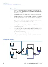
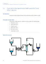
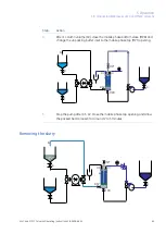
Page 50: ...n The operation of BioProcess LPLC and MPLC columns consists of the following steps Priming the column Preparing the slurry Filling the column Packing the column Running the column Unpacking the column General overview MPB MPT BSV 1 2 3 4 5 6 7 HI HO 50 LPLC and MPLC Columns Operating Instructions 28 9638 66 AC 5 Operation 5 1 Overview of the operation of BioProcess LPLC and MPLC columns ...

Page 51: ... Filling pump membrane pump 3 Pressure gauge 4 Pressure relief valve 5 Hydraulic fluid tank 6 Packing pump rotary lobe or equivalent 7 Hydraulic outlet HO Hydraulic inlet HI Mobile phase top valve MPT Bottom slurry valve BSV Mobile phase bottom valve MPB LPLC and MPLC Columns Operating Instructions 28 9638 66 AC 51 5 Operation 5 1 Overview of the operation of BioProcess LPLC and MPLC columns ...

Page 52: ...th hydraulic fluid or other bacteriostatic solution before the hydraulic chamber priming pro cedure is performed To perform hydraulic chamber priming follow the steps described below MPB MPT C B D A BSV HO HI Action Step Connect the column and tanks as shown in the above illustration 1 Open the hydraulic chamber inlet HI and outlet HO 2 52 LPLC and MPLC Columns Operating Instructions 28 9638 66 AC...

Page 53: ...column mobile phase priming follow the steps below MPB C B A BSV HI MPT HO Action Step Connect the column and the tanks as shown in the illustration above 1 Begin by priming the slurry line to the filling pump with water to remove air When there is no air remaining in the slurry line close valve B 2 Open the bottom slurry valve BSV 3 Open the mobile phase top valve MPT 4 Open the water tank valve ...

Page 54: ...e MPT Air will then be removed from the bottom bed support 7 When the air has been removed from the bottom bed support close the mobile phase bottom valve MPB and turn off the filling pump 8 54 LPLC and MPLC Columns Operating Instructions 28 9638 66 AC 5 Operation 5 2 Priming the column ...

Page 55: ...n the target bed height and compression factor The slurry media should be kept homogeneous using a manual or automatic stirrer When preparing the slurry for column filling make sure to prepare an excess amount to compensate for the compression factor applicable to the media used Tip Filling a column with slurry MPB C B A BSV HI MPT HO To fill a column with slurry LPLC and MPLC Columns Operating In...

Page 56: ...ure that all media is pumped into the column When all of the media has entered the column stop the pump 4 NOTICE Do not allow air to enter the filling lines or the column Close the bottom slurry valve 5 Close the hydraulic outlet 6 It is recommended that column packing is performed immediately after the column filling step This will avoid the settlement of media which may nega tively affect column...

Page 57: ...n packing step This will avoid the settlement of media which may negatively affect column performance Tip NOTICE Make sure the hydraulic chamber has been primed before begin ning to pack the media For more information about priming the hydraulic chamber see Section 5 2 Priming the column on page 52 Note To pack a column with media slurry follow the steps described below MPT C B D A BSV HI HO MPB L...

Page 58: ...ratedoutside these limits the equipment may be damaged and bodily injury or death may occur Adjust the pressure to a maximum packing pressure appropriate for the media and column 7 NOTICE Packing pressure and flow rate requirements depend on the media being packed Always refer to the media user manual to check for specifc packing advice Stop the packing procedure when the adapter reaches the prede...

Page 59: ...NOTICE Refer to the media user manual for expected HETP result information LPLC and MPLC Columns Operating Instructions 28 9638 66 AC 59 5 Operation 5 4 Column packing ...

Page 60: ...column must be disconnected from the priming and packing equipment At this stage the column may also be moved if required for connection of MPT and MPB to a BioProcess system NOTICE Check that tubing and connection diameters are compatabile before connecting a column to a BioProcess system To avoid reduced chromatography performance keep tubing connections as short as possible when connecting a co...

Page 61: ...ystem Action Step Connect tubing between the column bottom and the system valve marked COLUMN BOTTOM 1 Connect tubing between the column top and the system valve marked COLUMN TOP 2 Set the system column valves to the UpFlow position 3 Using the pump fill the system with an appropriate liquid for column instal lation 4 When the system including the tubing connected to the column is filled with liq...

Page 62: ...g sequence When the pump is started the system must be in Column UpFlow position If the column will be run in downwards mode after the connection the tubing con nected to the column top must also be filled with liquid before it is connected to the column top 62 LPLC and MPLC Columns Operating Instructions 28 9638 66 AC 5 Operation 5 5 Connecting a packed column ...

Page 63: ...osen over a period of time before being pushed out as slurry through the bottom slurry valve Media slurry is used to aid the unpacking procedure to avoid the need to use larger tanks for unpacking buffer or water Note Residual slurry is removed from the column by repeatedly pumping unpacking buffer or water through the bottom and top mobile phase openings until the column is clean Unpacking a colu...

Page 64: ... at a flow rate of 50 The water or unpacking buffer will enter the column through the mobile phase bottom opening Hydraulic liquid will be removed from the hydraulic chamber through the hydraulic outlet and the adapter will move upwards 3 64 LPLC and MPLC Columns Operating Instructions 28 9638 66 AC 5 Operation 5 6 Unpacking BioProcess LPLC and MPLC columns ...

Page 65: ... top MPT opening 4 MPB C B D A BSV HI HO MPT Stop the pump after 0 5 CV Close the mobile phase top opening and allow the packed bed to loosen for around 2 to 5 minutes 5 Removing the slurry MPB MPT C B D A BSV HI HO LPLC and MPLC Columns Operating Instructions 28 9638 66 AC 65 5 Operation 5 6 Unpacking BioProcess LPLC and MPLC columns ...

Page 66: ...g against a packed or sedimented bed stop the pump 4 Use the slurry to continue the unpacking of the column This avoids the need to use large volumes of unpacking buffer and larger buffer tanks 5 Open the hydraulic outlet 6 Connect the slurry tank to the filling pump membrane pump to the bottom slurry valve Keep the hydraulic inlet HI and the mobile phase top and mobile phase bottom openings close...

Page 67: ...inside of the column and remove residual slurry Continue pumping until the outlet is free from slurry 5 Connect the mobile phase top valve MPT to the packing pump 6 Close the mobile phase bottom valve MPB 7 Start the pump at a rate of 100 This will flush the top bed support and remove residual media 8 Stop pumping when the column is clean 9 LPLC and MPLC Columns Operating Instructions 28 9638 66 A...

Page 68: ...his chapter contains the following sections See page Section 71 6 1 Disassembling the column 74 6 2 Changing O rings and seals 86 6 3 Assembling the column 89 6 4 Cleaning and storage Precautions EX WARNING EXPLOSION HAZARD When a BioProcess LPLC or MPLC column is operated or maintained in a potentially explosive atmosphere it MUST be properly grounded to avoid static discharge 68 LPLC and MPLC Co...

Page 69: ...ARNING Do not perform any type of maintenance work on the column while the adapter is in motion Do not reach inside the column while moving the adapter To avoid serious bodily damage the adapter must be fully stopped and unable to move before work can be performed inside the column WARNING For continued protection against injury risks due to fluid jets burst pipes or explosive atmosphere the pipin...

Page 70: ...uid in the column during the leakage test Do not perform a leakage test on a column containing media CAUTION Take care not to scratch any steel surfaces of the column when removing seals and O rings NOTICE To retain sanitary surfaces it is recommended that clean gloves be worn whenever working with the column and especially whenever replacing O rings or working with internal column components 70 L...

Page 71: ... size for column components containing warm 50 C water Waste tubing and waste containers Wrenches Hex Allen keys 100 ethanol for cleaning and lubricating Clean rubber gloves to prevent grease from fingers becoming transferred to metal surfaces Removing the top end plate and adapter The top end plate and adapter are removed most easily as one unit Before beginning to disassemble the column make sur...

Page 72: ...place on the column tube 3 Continue pumping fluid into the column at a low flow rate via the bottom mobile phase valve This will cause the adapter and top plate to be pushed out of the column tube Take up any slack in the hoist crane cable Stop the pump when the adapter and top end plate are free 4 Rest the adapter and top end plate on supporting blocks as soon as they have been removed from the c...

Page 73: ... and raise the device until it contacts the surface of the bottom end plate Note Blocks may be placed between the lifting device and the bottom end plate to achieve the required lifting height 3 Use a wrench to remove the bolts holding the bottom end plate in place on the column tube 4 Carefully lower the lifting device The bottom end plate should detach from the column tube 5 If the bottom end pl...

Page 74: ...diameter wire approximate length 20 mm O rings seals and excluders 100 ethanol for cleaning 20 ethanol for lubricating seals Warm water approximately 50 C Packing house The packing house is located on the upper surface of the top end plate and forms the opening through which the adapter rod passes NOTICE Take care not to scratch any steel surfaces of the column when removing seals and O rings If s...

Page 75: ...ng a length of wire 2 mm diameter approximate length 20 mm into the groove surrounding the O ring and picking the O ring out 3 Clean the inside of the packing house and lubricate the new step seal and O ring with ethanol 4 Place the new O ring into the groove in the packing house 5 LPLC and MPLC Columns Operating Instructions 28 9638 66 AC 75 6 Maintenance 6 2 Changing O rings and seals ...

Page 76: ... of top end plate A Hydraulic chamber B Surface adapter rod C Step seal in correct orientation D O ring E Inner surface of packing house F Gently bend the O ring step seal as shown in the diagram Avoid bending sharply 7 Carefully press the folded step seal into place over the O ring 8 Mount a new excluder onto the packing house 9 76 LPLC and MPLC Columns Operating Instructions 28 9638 66 AC 6 Main...

Page 77: ...a sharp knife cut the existing O ring A and remove it 1 A Mount a new O ring onto the top end plate Tip Warming the new O ring in warm water 50 C will make it more pliable and easier to mount onto the top end plate 2 LPLC and MPLC Columns Operating Instructions 28 9638 66 AC 77 6 Maintenance 6 2 Changing O rings and seals ...

Page 78: ...cription Part O ring and protective seal A Leak detection system aperture B O ring and protective seal C Bed support seal D Carefully remove the upper bed support by pulling off the seal holding this in place 2 Remove the liquid distributor by unscewing the attachments and sliding the distributor out 3 Remove and replace the O ring on the distributor Using a sharp knife cut through the two seals t...

Page 79: ... bed support seal It may be necessary to warm the seal by placing it in warm water 50 C before replacing 8 Adapter rod There is an O ring under the adapter rod in the region of contact between the rod and the adapter To change this O ring Action Step Make sure that the adapter and the adapter rod are resting on a stable surface 1 Remove the bolts from the base of the adapter rod using a Hex Allen ...

Page 80: ...se the O ring A 3 A Remove the used O ring clean the surfaces with 100 ethanol and mount a new O ring in place 4 Replace the adapter rod housing cover and bolt into place 5 80 LPLC and MPLC Columns Operating Instructions 28 9638 66 AC 6 Maintenance 6 2 Changing O rings and seals ...

Page 81: ...t must be changed periodically To change the O rings and protective seal on the bottom end plate Action Step Remove the seal holding the lower bed support in place This will expose the bed support O ring that the seal protects 1 A B C Description Part Lower bed support A Lower bed support seal B Bottom end plate O ring C LPLC and MPLC Columns Operating Instructions 28 9638 66 AC 81 6 Maintenance 6...

Page 82: ...ription Part Lower bed support A Bed support O ring groove B Seal groove C Bottom end plate O ring D Remove the O ring from the outer circumference of the bottom end plate 3 82 LPLC and MPLC Columns Operating Instructions 28 9638 66 AC 6 Maintenance 6 2 Changing O rings and seals ...

Page 83: ...se inlet The compressed air will cause the liquid distributor to rise upwards 5 Remove the O ring from the liquid distributor and clean the surfaces of the liquid distributor with 100 ethanol 6 Place a new O ring on the liquid distributor and replace the distributor fittings in their mounts 7 Lower the liquid distributor onto the bottom end plate and bolt it into position 8 Mount a new O ring into...

Page 84: ...an the other It is important that the thinner edge of the seal is uppermost with the thicker edge of the seal snugly fitted into the groove directly under the bed support O ring Lower slurry valve The lower slurry valve has two O rings that are located as shown A in the illustration below A To change these O rings Action Step Remove the TC clamp on the valve 1 Pull out the valve to remove it from ...

Page 85: ...hanol 4 Lubricate the new O rings with 20 ethanol and then fit the O rings into position 5 Reinsert the valve and fix into position with the TC clamp 6 LPLC and MPLC Columns Operating Instructions 28 9638 66 AC 85 6 Maintenance 6 2 Changing O rings and seals ...

Page 86: ...a mechanical lifting device underneath the column Contact your GE Healthcare represen tative for information about lifting devices suitable for different column types To replace the bottom end plate Action Step Place a suitable mechanical lifting device under the bottom end plate Note Blocks may be placed between the lifting device and the bottom end plate to achieve the required lifting height 1 ...

Page 87: ...detection tubing between the top end plate and the adapter 2 Carefully lower the top end plate until it rests on top of the adapter 3 Screw the locking nut onto the tip of the adapter rod 4 Remove the fittings of the crane hoist from the top end plate and attach these to the eyes on the locking nut at the tip of the adapter rod 5 Fitting the adapter and top end plate into the column The adapter an...

Page 88: ...apter and top end plate into the column lowering the crane hoist as necessary 3 Insert the bolts when the adapter and top end plate have entered the column sufficiently Use a wrench to successively tighten the bolts using equal amounts of torque 4 88 LPLC and MPLC Columns Operating Instructions 28 9638 66 AC 6 Maintenance 6 3 Assembling the column ...

Page 89: ...rnal surfaces should not normally accumulate any substantial amount of dust or dirt GE Healthcare recommendsusing 20 ethanol to clean surface residues from the outside of the column as required but particularly after unpacking or performing maintenance procedures Cleaning in place CIP The appropriate cleaning in place methods for packed BioProcess LPLC and MPLC columns are determined by the specif...

Page 90: ...bout specific media Avoid any solution that may compromise the quality of the chromatography media In general storage solutions should be changed at regular intervals for example monthly if the column is intended to be stored for longer periods of time Always refer to your media user manual for media specific recommendations 90 LPLC and MPLC Columns Operating Instructions 28 9638 66 AC 6 Maintenan...

Page 91: ...he column bed supports blocked Air may be trapped in the bed support Always wet before use Is there any equipment in use either before or after the column which could generate back pressure For example is an adequate size of flow cell being used Are there differences in internal diameter between the tubing on the column the tubing from the pump or anywhere else in the system Do the gaskets and tub...

Page 92: ...a change in how the sample has been handled prior to its application to the column For example are there sample batch variations In the process have any changes been made to the following nets separation media time intervals be tween different operations buffer constituents precipitation procedures chromato graphic system hardware Any such changes should be analyzed for their effect on the chromat...

Page 93: ...Pump a solution that is a few degrees Celsius warmer than the media upwards through the column 1 Test the column again before using 2 LPLC and MPLC Columns Operating Instructions 28 9638 66 AC 93 7 Troubleshooting ...

Page 94: ...tation package delivered with BioProcess LPLC and MPLC columns Please refer to the Equipment Data Sheet EDS in the documentation package for the specific data for your column Measurement requirement Property Range in bar g Operating pressure Value in bar g Design pressure Range in l h Flow Range in bar g Compressed air Hydraulic Adapter operation Horizontal 1 Floor inclination Dimensions and weigh...

Page 95: ...d Extreme oxidizers Fluorine and halogenated compounds Chlorinated solvents such as methylene chloride Esters Aromatic hydrocarbons such as toluene Alcohols at concentrations higher than those specified in the table below Chloride solutions in combination with pH below 4 Always wash the column with at least five column volumes of a pH neutral solution water between and after use of chloride soluti...

Page 96: ...s of agents have not been taken into account in this table The applicable chemical resistance depends on the configuration of the column and the associated materials of construction WARNING Some of the chemicals listed below may be flammable under cer tain conditions Make sure to use the chemicals under conditions where they are not flammable Refer to local and or national clas sifications of flam...

Page 97: ...tainless steel bed supports 8 h 5 Phosphoric acid 7647 14 5 2 C to 30 C Purification CIP 3 h 0 to 3 M Sodium chloride 1310 73 2 2 C to 30 C CIP 24 h room temp to 30 C 1 M pH 14 Sodium hydroxide 1310 73 2 2 C to 30 C Storage 12 months 0 01 M pH 12 Sodium hydroxide 1310 73 2 64 17 5 2 C to 30 C CIP 3 h 1 M 20 Sodium hydroxide ethanol 7757 82 6 2 C to 30 C Adsorption 3 h 1 M Sodium sulphate 57 13 6 2...

Page 98: ...ese solutions depends on the pH of the buffer which can vary between 3 to 13 For columns containing wetted stainless steel components a maximum concentration of 1 0 M NaCl is recommended Please also refer to the Resistance to sodium chloride section above for further information Not for use with columns containing wetted stainless steel components 98 LPLC and MPLC Columns Operating Instructions 28...

Page 99: ...hutdown 29 End plate Bottom plate 81 Top plate 77 F Filling a column with slurry 55 Filling pump 51 G General connection guide lines 48 General technical specifica tions 94 H High back pressure 91 Hydraulic chamber priming 52 Hydraulic fluid connections 48 Hydraulic inlet 51 Hydraulic outlet 51 I International standards 10 L Label Label on column 26 Labels Safety labels 28 Leakage 91 Levelling the...

Page 100: ... compression 55 Slurry preparation 55 Slurry valve Lower 84 Space and floor load 29 Storage 90 T Top end plate Fitting 87 Transport unpacked 40 Transport in crate 40 Typographical conventions 6 U Unpacking instructions 42 User information important 7 100 LPLC and MPLC Columns Operating Instructions 28 9638 66 AC Index ...

Page 101: ......

Page 102: ...e on request Contact your local GE Healthcare repre sentative for the most current information GE Healthcare Europe GmbH Munzinger Strasse 5 D 79111 Freiburg Germany GE Healthcare UK Limited Amersham Place Little Chalfont Buckinghamshire HP7 9NA UK GE Healthcare Bio Sciences Corp 800 Centennial Avenue P O Box 1327 Piscataway NJ 08855 1327 USA GE Healthcare Japan Corporation Sanken Bldg 3 25 1 Hyak...

Reviews: