background image


                                                                                                                                                               5358651-1EN 


                                                                                                                                                               Rev. 18 

                                                                                                                                                                                © 2021 

                                                                                                                                                                                General Electric Company 


All Rights Reserved 

For USA, OEC Brivo Prime/OEC Brivo Essential/OEC Brivo Plus are respectively described as 

Brivo OEC 715/Brivo OEC 785/Brivo OEC 865 in the manual.


GE Healthcare 


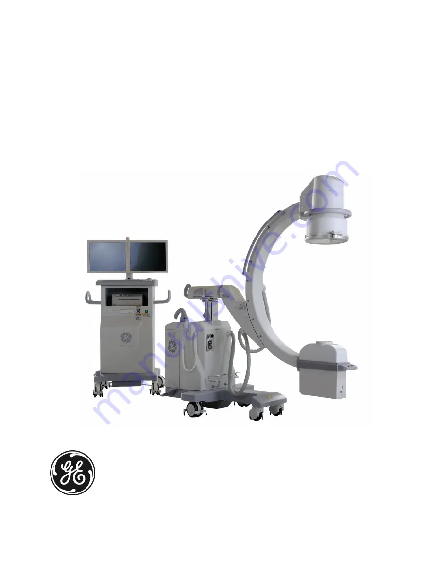
Mobile C-arm X-ray Product 

Service Manual 
Brivo OEC 715/Brivo OEC 785/Brivo OEC 865 


Summary of Contents for Brivo OEC 715

Page 1: ...hts Reserved For USA OEC Brivo Prime OEC Brivo Essential OEC Brivo Plus are respectively described as Brivo OEC 715 Brivo OEC 785 Brivo OEC 865 in the manual GE Healthcare Mobile C arm X ray Product S...

Page 2: ......

Page 3: ...f this manual was originally written approved and published by the manufacturer in English GE HUALUN Medical Systems Co Ltd a General Electric company going to market as GE Healthcare GE HUALUN Medica...

Page 4: ...5 Brivo OEC 865 complies with the regulatory requirements of the following Council Directive 93 42 EEC concerning medical devices CE label affixed to the product testifies compliance to all requiremen...

Page 5: ...d Section 8 6 2 EC4 Power indicator LED check Section 3 5 3 EC5 Auto technique tracking Section 3 6 3 and Section 8 8 2 EC6 Pre Installation Section 3 2 EC7 Monoblock replacement Section 7 3 7 EC8 I I...

Page 6: ...vatelj usluge klijenta treba neki drugi jezik klijent je du an osigurati prijevod Ne poku avajte servisirati opremu ako niste u potpunosti pro itali i razumjeli ovaj servisni priru nik Zanemarite li o...

Page 7: ...vigastamist elektril gi mehaanilise v i muu ohu tagaj rjel VAROITUS FI T m huolto ohje on saatavilla vain englanniksi Jos asiakkaan huoltohenkil st vaatii muuta kuin englanninkielist materiaalia tarv...

Page 8: ...ngum ls en ensku er a skylda vi skiptamanns a skaffa tungum la j nustu Reyni ekki a afgrei a t ki nema a essi j nustuhandb k hefur veri sko u og skilin Brot sinna essari a v run getur leitt til mei sl...

Page 9: ...ienta Nie pr bowa serwisowa urz dzenia bez zapoznania si z niniejszym podr cznikiem serwisowym i zrozumienia go Niezastosowanie si do tego ostrze enia mo e doprowadzi do obra e serwisanta operatora lu...

Page 10: ...ancia del presente aviso puede dar lugar a que el proveedor de servicios el operador o el paciente sufran lesiones provocadas por causas el ctricas mec nicas o de otra naturaleza VARNING SV Den h r se...

Page 11: ...plosion 5 1 2 5 Thermal hazards 6 1 2 6 Equipment Stability 6 1 2 7 X Radiation 6 1 2 8 Motorized Mechanical Movement 7 1 2 9 Work on Parts with Lead Materail 7 1 2 10 Safety Interlock 7 1 2 11 Labels...

Page 12: ...1 3 1 Overview 3 2 3 2 Pre Installation 3 2 3 2 1 Dimensions and Weights of System 3 2 3 2 2 Site Requirement 3 2 3 2 3 Power Supply Requirement 3 3 3 2 4 Environments 3 3 3 2 5 Tools and Test Equipme...

Page 13: ...9 3 7 1 CD DVD Burner Installation 3 49 3 7 2 Laser Aimer 3 50 3 7 3 Video Distributor 3 53 3 7 4 Printer 3 57 3 7 5 Film cassette holder 3 59 3 7 6 Tube Skin Spacer 3 60 3 7 7 Pedal Switch 3 61 3 7 8...

Page 14: ...ize Collimator Iris Field Size 4 41 4 6 7 ABS Tracking Check and Adjustment 4 42 4 6 8 Limiting Resolution 4 45 4 6 9 Shading Correction Check and Calibration 4 51 4 7 DAP Accuracy Verification and Ca...

Page 15: ...6 2 Error Recovery Steps 6 2 6 3 Event Messages 6 2 6 3 1 Structure of Message Code 6 2 6 3 2 Definition of Code 6 3 6 3 3 Message List 6 5 6 4 Troubleshooting Guide 6 68 6 4 1 Workstation and Control...

Page 16: ...Actuator 5075921 7 67 7 3 22 Switches 7 71 7 3 23 Orbital Rolling Wheels Kit PN 5599917 7 74 7 3 24 Others 7 75 Chapter8 Periodic Maintenance 8 1 8 1 Overview 8 2 8 1 1 Safety 8 2 8 1 2 Tools and Test...

Page 17: ...eck 8 16 8 9 2 DAP Accuracy Check 8 16 8 10 Reporting 8 16 8 10 1 Install Equipment Covers 8 16 8 10 2 Complete PM Comments 8 16 Chapter9 Technical Reference 9 1 9 1 Overview 9 2 9 2 System Specificat...

Page 18: ...6 9 4 2 Single Load Ratings 9 12 9 4 3 Thermal Characteristic 9 13 9 5 Radiation Safety Specification 9 14 9 5 1 Scatter Data 9 14 9 5 2 Scatter radiation specification 9 15 9 6 Material Safety Data S...

Page 19: ...Chapter1 Introduction and Safety...

Page 20: ...systems Factory trained service personnel will benefit the most from this material 1 1 5 Unauthorized Modifications GE HUALUN Medical Systems Inc certifies that when assembled according to the manufac...

Page 21: ...e Provides procedures for software maintenance and service mode utilities Troubleshooting Provides error code error messages and diagnostic programs that expedite the diagnostic process Replacement Re...

Page 22: ...of data NOTE is given in situation requiring special attention 1 2 2 Ingress of Fluids Excessive amounts of fluids such as antiseptics cleaning solutions or bodily fluids may damage internal component...

Page 23: ...ong periods after power has been removed Some devices can acquire a charge spontaneously without direct contact with other circuitry Do not touch these components unless power has been completely remo...

Page 24: ...ransport position and lock brake handles prior to moving the equipment Use the handles designed for moving the equipment and mechanical assemblies Never attempt to move the system up or down steps Do...

Page 25: ...o not carelessly place objects on the equipment or bump or lean against the equipment Observe and prevent articles of clothing from getting caught in moving parts 1 2 9 Work on Parts with Lead Materai...

Page 26: ...the Wig Wag brake is locked 2 1 This label indicates the position of the C Arm rotation handle When the handle is rotated to the dashed position the brake is released When the handle is in solid line...

Page 27: ...This label indicates the position of the C Arm horizontal movement handle When the handle is rotated to the dashed position the brake is released When the handle is in solid line position the brake is...

Page 28: ...l is attached on the control panel to note that please refer to operator manual to operate the control panel This label is attached by UPS shut down button to avoid misusing Only when UPS can t shut d...

Page 29: ...ointed device only This port is only used for user to store patient image by USB disk Any other equipment is forbidden to be connected strictly 16 1 This label on the footswitch means that the degree...

Page 30: ...Brivo OEC 715 785 865 Mobile C Arm X Ray Product Service Manual 12 18 2 System rating plate indicates manufacture information and input power requirements 19 1 Generator tube head rating plate...

Page 31: ...Introduction and Safety 13 Total filtration label 20 1 This is the label of collimator 21 1 This is the label of laser warning The label will only be required if there is laser aimer...

Page 32: ...and was found to be in compliance with the requirements of all relevant directives and standards in effect within the European Union at the time of manufacture 24 1 This label indicates that waste el...

Page 33: ...of the device 150700 Manufacturing date year month day YYMMDD with DD always equal to 00 21 GS1 application identifier for the serial number of the device AAAAAYY00001AA Serial number 27 1 This label...

Page 34: ...65 Mobile C Arm X Ray Product Service Manual 16 29 1 USB warning label 30 1 C Arm weight label 31 1 Workstation weight label 32 1 Image Intensifier label for Brivo OEC 715 785 1 Image Intensifier labe...

Page 35: ...for Brivo OEC 715 785 865 33 2 Hg label is attached on the monitor back 34 1 removable copper 0 1mm Cu 35 1 removable Grid 36 1 skin spacer 37 1 This label indicates the system complies with the Braz...

Page 36: ...is label indicates the key switch Turn the key switch located on the C arm interface panel to enable X Rays and motorized mechanical movement 39 1 This is the label of functional earth ground connecti...

Page 37: ...1 This is the label of fuse 44 1 This is the label of J3 connector Remove the workstation back cover The label is near the connector on the bottom 45 1 PLC label 46 1 DC BUS fuse label 47 1 WIFI labe...

Page 38: ...rcuit Breaker or other over current protector used in power supply for this product shall meet the requirements 50 1 This warning label is on the Workstation front cover 51 2 Packing label 52 2 Brivo...

Page 39: ...Introduction and Safety 21 53 1 Spot Film Device label 54 1 This is the label of collimator Remove the tube head cover This label is on the collimator...

Page 40: ...Brivo OEC 715 785 865 Mobile C Arm X Ray Product Service Manual 22 1 2 12 Locations of the Labels 5 3 4 2 14 25 21 22 32 25 6 7 8 1 17 39 28 14 19 11...

Page 41: ...Introduction and Safety 23 46 54 20 18 26...

Page 42: ...Brivo OEC 715 785 865 Mobile C Arm X Ray Product Service Manual 24 13 10 15 18 49 31 27 24 45 23 40 41 41 44 43 47 48 12 52 15 29 50...

Page 43: ...n earth ground connection that is necessary to maintain grounding throughout the system X Ray Source This X Ray Source symbol is used to identify controls that will produce ionizing X radiation when a...

Page 44: ...rm X Ray Product Service Manual 26 Type B This symbol indicates the equipment is protected against electric shock by a protective earth ground connection Ionization Radiation This symbol indicates tha...

Page 45: ...elow If this equipment is found to cause interference which may be determined by switching the equipment on and off the operator or qualified service personnel should attempt to correct the problem by...

Page 46: ...Product is intended to use in the specified electromagnetic environment The purchaser or operator of the Brivo OEC 715 785 865 Mobile C arm X ray Product should assure that it is used in an electroma...

Page 47: ...for input output lines Mains power quality is that of a typical commercial and or hospital environment Surge IEC 61000 4 5 1 kV Line s to Line s 2 kV Line s to earth 1kV Line s to Line s 2 kV Line s t...

Page 48: ...ower rating of the transmitter in watts W according to the transmitter manufacturer and d is the recommended separation distance in meters m Field strengths from fixed RF transmitters as determined by...

Page 49: ...nce by the recommended separation distance below Rated Power of Transmitter W Separation Distance m 150KHz to 80 MHz P d 3 5 3 80 MHz to 800 MHz P d 3 5 3 800 MHz to 2 5 GHz P d 3 7 0 01 0 12 0 12 0 2...

Page 50: ...d 13 17 Pulse modulation b 217 Hz 0 2 0 3 9 745 780 810 800 960 GSM 800 900 TETRA 800 iDEN 820 CDMA 850 LTE Band 5 Pulse modulation b 18 Hz 2 0 3 28 870 930 1 720 1 700 1 990 GSM 1800 CDMA 1900 GSM 19...

Page 51: ...distance in m and E is the IMMUNITY TEST LEVEL in V m Use Recommendations This product complies with IEC 60601 1 2 EMC standard for medical devices and with radio frequency emission requirements per C...

Page 52: ...TO Authorized and initial LOTO Verification training will be permitted to execute Lockout Tagout on this system All other non authorized individuals will be considered affected individuals Specific So...

Page 53: ...ollowing components unexpected gravitational energy can be released Removing the X Ray tube image intensifier or the C weldment can cause the rear of the C arm to tilt and hit the floor Place a block...

Page 54: ...ct contact with other circuitry Do not touch these components unless power has been completely removed and they have been discharged Equipment that contains high power electrical components must be se...

Page 55: ...Chapter2 System Overview...

Page 56: ...ns can operate this equipment Brivo OEC 715 785 865 Mobile C Arm X ray Product includes Mobile C Arm high frequency X Ray generator Image intensifier GigE CCD camera and console Collimator Mobile Work...

Page 57: ...together are commonly called the C and the entire assembly from the casters up is known as the C Arm The X Ray tube generates an X ray beam that is shaped and oriented by the collimator After passing...

Page 58: ...movement brake handle 4 Skin spacer 5 X ray tube head X ray tube and collimator 6 Front wheel 7 Rear wheel 8 Wig wag movement brake handle 9 Steering handle 10 Horizontal movement brake handle 11 C a...

Page 59: ...heel 7 LCD Monitors 8 Workstation membrane keyboard 9 DVD driver 10 Brake pedal 11 Central control wheel 12 Handles 13 Room Control Connector 14 Network interface 15 Wireless network interface switch...

Page 60: ...Brivo OEC 715 785 865 865 Mobile C Arm X Ray Product Service Manual 2 6 System block System Schematics please refer to appendix...

Page 61: ...etween C Arm and the Workstation is removed or any PCBs in C Arm loose from slot due to collision or other unexpected situation the relay K4 on Power Distribution Unit Board will not be energized so t...

Page 62: ...ame Power On Board 24V When the main input power is ok with no gross over and under voltage condition the relay K6 is activated and the AC voltage of secondary side of start_up transformer BT2 is appl...

Page 63: ...tate Detection and Signal Drive Circuit The Intelligent Power Control Unit UPS control logic The power on board comes from the output of the start up transformer and generates the necessary DC power l...

Page 64: ...3 will be energized for about 1s to avoid the risk that the resistor R will be heated and burned when the K4 is in failure The 28V voltage winding is directly applied by the relay K5 UPS status for Po...

Page 65: ...R_12V Heartbeat 2s 1s 1s 1s 2s 350ms 2s 1s Normal power on timing Normal power off timing Air Interface AC power input AC power input is listed as follows Name Description Pin Attribution Scale Commen...

Page 66: ...Scale Comment SEC_TRANS_220V_L Output of secondary side of main transformer PJ2 3 Power 100 110 120 200 220 230 240VAC SEC_TRANS_220V_N PJ2 6 SEC_TRANS_28V_L PJ2 1 Power SEC_TRANS_28V_N PJ2 4 Mainfram...

Page 67: ...wer on off switch interface The switch on off signal for PC are listed as follows Name Description Pin Attribution Scale Comment CMPTR_CTRL_1 PC ON OFF Control PJ10 1 signal CMPTR_CTRL_2 PJ10 2 signal...

Page 68: ...CK_PDU2SIB acknowledge signal between PDU and SIB PJ8 21 digital 0 12V 6V High SYS_PWR_OFF_CMD system power off command PJ8 22 digital 0 12V 6V High SYS_PWR_OFF_DENY system power off deny command PJ8...

Page 69: ...nt for analog circuit TP25 GNDA Reference point for analog circuit LEDs Name Color Description HL1 Green 3 3V power indicator HL2 Green 5V power indicator HL4 Red Secondary side over voltage fault ind...

Page 70: ...cables to or from Collimator Display Board KV Control Board Sealing Board I I Hand Switch Footswitch Emergency Key Switch Filament DC Power Supply Boxes Laser Aimer etc Offer interfaces and installat...

Page 71: ...erfacing with collimator board filament board and KV control board Image chain control control camera and image intensifier User interface key input and LED display interfacing with display board Syst...

Page 72: ...munication with Workstation Communication with peripheral controller to report the working status of MCU Peripheral controller function Sample the status of input pins and record them into status regi...

Page 73: ...ve by power supply 1 2 via mother board and 3 3V 2 5V 1 2V are generated from 5V_PS1 Power supplies are listed as follows Name Description Source Scale Pin Comment 5V_PS1 5V power supply PS1 5V J2 A5...

Page 74: ...respectively The outputs of those circuits are added by signal mA_preheat then the result signal MAC is output to filament control board The theory of PI control circuit is as follows The tube current...

Page 75: ...emperature of oil tank is higher than a preset threshold the relationship between THERMAL_SWITCH_A and THERMAL_SWITCH_B changes from connected to open This relationship is transformed by optical coupl...

Page 76: ...fferent routes Foot Switch The circuit and theory are similar to hand switch include checking the switch stuck error Emergency Switch The circuit and theory are similar to voltage transmit circuit Rem...

Page 77: ...ing Auto mA Calibration Because valid exposure period in each frame is smaller than 40 ms response time from MAC signal set out to mA stable should be within a certain time Meanwhile the response time...

Page 78: ...5V J1 C19 SPI_SYNC_CCB SPI chip select signal Digital 0V 15V J1 A21 15V effective RSV_CCB Reversed for future Digital 0V 15V J1 B15 Signals from collimator control board to MCB are listed as follows N...

Page 79: ...Digital 0 15V J1 B18 0V effective KV_UNBALANCE_ALM_N KV unbalance in two bridges of inverter Digital 0 15V J1 C18 0V effective KV_FEEDBACK_OUTPUT KV sample value from KV control board Analog 0 6V Uni...

Page 80: ...2 B2 C2 II_GND Reference of power Power 0V J1 A3 B3 C3 Sealing Board Signals from sealing board to MCB are listed as follows Name Description Attribution Scale Pin Comment OIL_TEMP Output voltage of t...

Page 81: ...anel Digital 0 15V J1 C24 SPI_ CS1 Chip select 1 for MAX9654 Digital 0 15V J1 A25 15V effective SPI_ CS2 Chip select 2 for MAX7301 Digital 0 15V J1 A28 15V effective LED_ YELLOW_N Yellow led lights si...

Page 82: ..._FLU button has been pressed FOOT_FLU_SECURIT Y Foot security line termination Passive Open Close J1 C28 FOOT_ HLF High Level Fluoro foot switch termination Passive Open Close J1 A14 FOOT_HLF FOOT_COM...

Page 83: ...signal Digital 0V 15V J1 B30 15V Filter removed Indicator Signals from MCB to indicator are listed as follows Name Description Attribution Scale Pin Comment XRAY_INDICATOR_A Anode of indicator Passiv...

Page 84: ...om FDB LED Indicators Reference Name Description D12 2V5 Light lights when 2 5V is available D13 1V2 Light lights when 1 2V is available D20 CAMR RXD485 RXD485 D20 on MCB lights normally and flickers...

Page 85: ...M FOOT_FLU_SECURITY FOOT_COM D47 lights when either HAND_FLU_SECURITY HAND_COM or FOOT_FLU_SECURITY FOOT_COM connected D48 RFB PROTECT_A D48 lights when one of two removeable filters is removed D52 HA...

Page 86: ...s and forbidden lamp by SPI BUS X ray in use lamp controlled by MCB directly 6 interface Button indicator light Interface to user Requirements The display board shall provide 17 button indicator light...

Page 87: ...15 5 Digital 0 15V DB_INT MAX6954 interrupt signal DB15 6 Digital 0 15V 0V effective GND_PS1 GND from MCB DB15 7 Ground GND INTERLOCK_B Interconnect with INTERLOCK_A DB15 8 Passive 15V_DB 15V from MCB...

Page 88: ...5 Digital open close close effective Alarm_ reset DX3_16 Digital open close close effective Pulse_ rate_ selection DX3_17 Digital open close close effective Pulse_ Enable DX4_1 Digital open close clos...

Page 89: ...ructure of KCB is shown as follows Power and USB signal The keyboard control board connects with the host computer of WKS by a USB cable the power and signal conform to the standard USB 1 1 protocol K...

Page 90: ...terface environment What we apply in this design is the USB interface and it supports the USB standard request as well as HID class request version 1 1 The pin assignment of HT82K629A is shown in Pict...

Page 91: ...DB_OVERCUR_N DOWN_PROTECT UDB_OVERCUR_N UDB_OVERCUR_N DRV UP_COMMAND DOWN_COMMAND J4 MOTO2 24V_UDB J5 J1 Motor Current Detector 1 3 Up down relays 1 4 M Proximity switch E2E X5ME2 NPN J6 1 5 4 2 3 5 2...

Page 92: ...ontrol relays This circuit is to control the relays in Up down relays circuit according to the commands from Up down Key Control Delay circuit Up down Key Control Delay This circuit is to translate th...

Page 93: ...motion When the motor is down to the proximity protect position the output of this circuit would be high level and the motor would be stopped Interlock Protector There are many factures to affect the...

Page 94: ...1 0V J3 2 Ground 0V Lift column motor interface The DC power supplies for the motion of the lift column motor are listed as follows Name Description Pin Attribution Scale Comment MOTO1 DC power to the...

Page 95: ...OWN_PROTECT_CON Proximity protect signal to control relay K9 TP4 GND_PS1 GND TP5 GND_PS1 GND TP6 GND_PS1 GND TP7 DC Voltage after rectification and regulation TP8 Motor current TP9 24V_UDB 24V voltage...

Page 96: ...F1 and 12V 1A F2 are used to protect computer ATX power Internal power to drive chips are divided from 5V three voltages 3 3V 2 5V and 1 2V are generated The signals come from and send to user interf...

Page 97: ...ound GND GND_Cmptr GND 7 Ground GND Computer Interface Signals communicate with computer in WKS are listed as follows Name Description Pin Attribution Scale Comment SIB_TxD SIB RS232 data send 2 Digit...

Page 98: ...indicate cable between SIB and PDU plug or not 10 Digital 0V 12V High effective Input Beep_Invalid_Key_Cm d Invalid key beep command 19 Digital 0V 12V High effective Output Intlc_Board Interlock statu...

Page 99: ...he SIB provides test points for following signals Name Description TP1 5V power TP2 3 3V power TP3 2 5V power TP4 1 2V power TP5 12V_Cmptr power TP6 5V_Cmptr power TP7 MF_Pwr_On_Cmd TP8 Rdy TP9 Sys_Pw...

Page 100: ...Manual 2 46 LED12 T_LED1 N A LED13 T_LED2 N A LED14 T_LED3 N A LED15 T_LED4 N A LED16 XRAY_ON_CMD_FB High effective LED17 ROOM_IN_USE_CMD_FB High effective LED18 WIRELESS_PWR_CMD_FB High effective LED...

Page 101: ...r IRIS MOT Driver IRIS MOT ROT MOT WIDT H MOT DIN SCLK SYNC Mother board 15V 15V 5V Power There are 5V 15V and 15V inputs 15V is used to drive OC input and all the OPA 15V is used to drive all the OPA...

Page 102: ...ck 0 15V Digital output J1 b14 IRIS_POS_F Transmit IRIS motor position analog feedback to MCB output 0 5V analog output J1 b13 SHUT_ROT_POS_F Transmit shutter rotation motor position analog feedback t...

Page 103: ...osition after filter TP12 Shutter rotation motor control TP13 Shutter rotation control after DAC TP15 Shutter width motor control TP16 Shutter width control after DAC TP18 IRIS motor control TP19 IRIS...

Page 104: ...of 5 function blocks refer to kV control board block diagram PWM GENERATOR KV control board provides PWM signal output SG3525A pulse width modulator control circuits offer Improved performance and low...

Page 105: ...or a complete isolated IGBT gate drive circuit with fault protection and feedback into one SO 16 package TTL input logic levels allow direct interface with a microcontroller and an optically isolated...

Page 106: ...nd kV absolute value in the monoblock is higher than 10kV the exposure is disable To the circuit when difference signal KVN is higher than the reference value in U18 2 the STOP signal is activated At...

Page 107: ...V too low alarm lower than 35KV Digital 0 15V 0V alarm KV_HIGH_ALM KV too High alarm higher than 120KV Digital 0 15V 0V alarm OVERCURRENT_ALM Inverter over current alarm Digital 0 15V 0V alarm IGBT_ER...

Page 108: ...tput of DC bus TP20 GD4 TP21 GD1 TP22 TOP1 TP23 GD2 TP24 BOT1 TP25 GD3 TP26 TOP2 TP27 GD4 TP28 BOT2 TP29 18V1 TP30 5V1 TP31 15V TP32 KV TP33 KV TP34 KV set TP35 10V TP36 KV low voltage alarm TP37 DC b...

Page 109: ...M control Filament select circuit Hall current detect Filament transformer current control L S focus switch 10V reference and Interlock Inverter The filament drive pulses PWMA and PWMB drive power MOS...

Page 110: ...R28 if the connection is broken Condition Filament FCSSW_FDB logic J7 Position Low small Small filament Low large Large filament High small Large filament High large Large filament Hall current detect...

Page 111: ...Power 24V 24V 24V_GND GND of 24V J1A 6 J1B 6 J1C 6 Ground GND GND of 24V MAC_FDB Set current value J1B 9 Analog 0V 15V PWMC_FDB Control voltage output J1B 13 Analog 15V 15V FILDIS_FDB Filament disabl...

Page 112: ...M control voltage 10V TP12 Power OSC TP13 crystal oscillator output PWMA TP14 PWM drive signal GND TP15 GND GND TP16 GND 24V_GND TP17 GND of 24V LED Name Color Pin Description 15V Green HL1 Power 15V...

Page 113: ...igh voltage circuit output 120kV to the tube The controller needs to get kV value and mA value from monoblock KV sense circuit comprises high voltage resistor R1 R4 and sense resistor R2 R3 The high v...

Page 114: ...nnected means that temperature is higher than threshold THERMAL_SWITCH_B The other termination of temperature switch Passive MA_CAT The cathode of mA sample Analog KV_GND The anode of mA sample Analog...

Page 115: ...2 3 Signals from Hand Switch to MCB Name Description Attribution Scale Pin Comment HAND_FLU Hand switch termination Passive Open Close J1 B28 HAND_FLU HAND_COM is connected means HAND_FLU button has p...

Page 116: ...the system At any time if the emergency switch is pushed down the X ray exposure shall be stopped immediately System shall trigger the related error message Name Description Attribution Scale Comment...

Page 117: ...image and exposure technique are produced Collimator Control Collimator The collimator is an electromechanical assembly designed to allow the operator to restrict the size and shape of the X ray beam...

Page 118: ...back will reduce The drive voltage returns almost zero while the feedback is very close to the command The control loop is finished Collimator control subsystem works in following situations a Move th...

Page 119: ...bsolute IEC 65 65 65 For PN 5085917 Parameters Operating Mode Unit Normal 9 Magn 1 6 Magn 2 4 5 Useful entrance field size 215 160 120 mm Output image diameter 25 2 mm Center Limiting resolution 52 58...

Page 120: ...ive mechanical parts GigE Camera GE1020A GigE Camera GE1020B GigE Camera GE1020C GigE Camera is above Image Intensifier It takes the image from the output of Image Intensifier The following are the ma...

Page 121: ...amera FPGA controls CCD driver electrical circuit to drive CCD sensor then CCD sensor transfers the optical signal into analog signal VGA and 12 bit ADC convert analog signal to digital signal FPGA bu...

Page 122: ...ut RS422 negative terminal of differential TXD signal 9 RXD485 Input RS422 positive terminal of differential RXD signal 10 VCC 12V supply voltage 11 GND GND 12 RSV Reserved 13 RSV Reserved 14 FrameSyn...

Page 123: ...is integrated into lens This interface flange provides three holes for mounting camera with image intensifier at the same time it provides 6 screws around flange to position the image center for accom...

Page 124: ...east 2 mm for positioning the image center GigE Camera GE1020B use Sysnix HKSC 1 lens This lens has 16mm focal lens manual iris F1 6 F11 and manual focus GigE Camera GE1020B uses an interface flange f...

Page 125: ...ual iris F1 4 F16 and manual focus GigE Camera GE1020C uses an interface flange for mounting itself into image intensifier This interface flange is independent part from lens This interface flange pro...

Page 126: ...f radiation and that with the Anti scatter Grid placed in the beam Setup points No setup points available Monitor There are 4 kinds of monitor for Brivo OEC 715 785 865 PN Name Comments 5075503 19 Inc...

Page 127: ...Size 19 0 Aspect Ration 5 4 Resolution 1280 x 1024 dots SXGA Maximum Brightness 800 Cd m2 min Contrast 600 1 min Viewing Angle H 170 degree V 170 degree Video Input Signal DVI D VGA OSD Control key M...

Page 128: ...on Backlight Black level Contrast Brightness level Position Size Phase Gamma DICOM etc Preset Brightness 500 20 Cd m2 600 20 Cd m2 700 20 Cd m2 Preset Display Curve DICOM CIE Gamma 1 8 Gamma 2 0 Gamma...

Page 129: ...e and user data The computer contains DVI D and HDMI output for monitor The DVI D is for left monitor and the HDMI is for right monitor The computer contains two Ethernet ports One is for CCD camera t...

Page 130: ...6 USB 2 0 ports One is for workstation s membrane keyboard one is from user interface extended to the front of workstation one is for touchscreen of 865 one is for UPS communication the remains are r...

Page 131: ...output capacity is 550VA 330W and can provide at least 2 minutes for computer and right monitor so that system can shutdown computer safely UPS is booted up or shut down by PDU board and communication...

Page 132: ...mand from the load has exceeded the capacity of the Back UPS 6 Event An event has occurred and the unit needs attention 7 Automatic Voltage Regulation The unit is compensating for extremely low input...

Page 133: ...he UPS to control when it will switch to battery power the higher the sensitivity the more often the unit will switch to battery power 1 Ensure the unit is connected to utility power but is OFF 2 Pres...

Page 134: ...Brivo OEC 715 785 865 865 Mobile C Arm X Ray Product Service Manual 2 80 Warnings and System Faults Warnings Press DISPLAY to scroll through the display screens System Faults...

Page 135: ...nction will not activate unless the UPS is operating on battery power Sensitivity 6 Off The Load Capacity icon will blink indicating that the unit is in programming mode Use the POWER button to scroll...

Page 136: ...ansfer voltage and sensitivity range The unit does not provide the expected amount of backup time Battery Backup outlets may be fully or improperly loaded Disconnect non essential equipment from the B...

Page 137: ...Chapter3 Installation...

Page 138: ...ons C Arm Hmax Hmin W L 215 170 5cm 78cm 179cm 84 6 67 1 30 7 70 3 Workstation H W L 167cm 64cm 90cm 65 7 25 35 4 Weights C Arm 260 10kg Workstation 170 10kg 3 2 2 Site Requirement Scan room H W L 2 8...

Page 139: ...And 20 A is required in Japan Suitable sockets are required both in Scan room and Operating room for maintenance Power supply should comply with requirement of the system power supply requirements The...

Page 140: ...2 head 2 Wrench Monkey wrench or wrench for M8 and M12 hexagon screw 3 Allen Keys 4 Dosimeter 5 10 12 Film 6 Blank CD DVD disk 7 Spatial Resolution Tool 8 Lead Apron thicker than 3mm 9 Pinchers 10 Sc...

Page 141: ...rews washers etc Once damage is observed notify service of the transportation and insurance company immediately If non apparent damage due to transportation was found during unpacking or installation...

Page 142: ...ng and box of the C Arm Then remove the seal wrapper of the C Arm 3 Remove the limitation frame of Image intensifier and Monoblock 4 Lock the cross arm Wigwag lateral rotation and orbital movement bra...

Page 143: ...remove the wood support as above picture After removing the wood support release central screw to land steering wheels on pallet and then remove the metal bracket Lock the steering brake before releas...

Page 144: ...secure screws of the metal bracket and wood support as below picture 8 Use wood crowbar prize the front base of C Arm to remove the wood support as below picture The wood crowbar shall prize below ar...

Page 145: ...e middle limitation block bracket 11 Loosen the bolt with a screwdriver and remove the horizontal cross arm lock device Loosen the horizontal movement brake handle and push the C Arm forward Lock the...

Page 146: ...es 3 Remove the screws on both sides as below 4 Lock the wheels to ensure the wheels to land on the wood support For Brivo OEC 718 785 lock all wheels of workstation For Brivo OEC 865 lock the central...

Page 147: ...Installation 3 11 7 Put the ramp in position Release all bracket and move the workstation along the ramp off the pallet...

Page 148: ...s that the Mobile C Arm s mechanical subassemblies position should be placed in their most compact position before transporting or moving the system 2 1 This label on the control panel of the C Arm in...

Page 149: ...3 13 4 2 System rating plate indicates manufacture information and input power requirements Check the rating plates to ensure mainframe and workstation serial numbers matched 5 1 Generator tube head...

Page 150: ...al 3 14 6 1 This is the label of collimator 7 1 This label warns the operator or the patient not to look at the laser beams directly The label will only be required if there is laser aimer 8 1 USB war...

Page 151: ...Installation 3 15 1 Image Intensifier label for Brivo OEC 865 10 1 Image Intensifier label 11 1 This warning label is on the Workstation front cover...

Page 152: ...Verify that Lemo Connector on cable mates well with the connector on C Arm and that there are no bent or missing pins AC Power Cord and Plug Verify that the AC power cord and plug supplied with the sy...

Page 153: ...Internal Inspection Observe electrostatic discharge safety procedures Removing any covers exposes dangerous electrical voltages on several components When possible disconnect system from AC line befo...

Page 154: ...1 Make sure that workstation rear cover was removed 2 Check the breaker power cable and plug are proper and relative to the power supply voltage 3 Input voltage option plug The short terminator is use...

Page 155: ...ransformer taps Voltage 240 V 230 V 220 V 200V 120V 110V 115V 100V Wire N Brown 1 1 1 1 1 1 1 Wire L1 Blue 5 4 4 3 5 4 3 Wire N1 Black 2 2 2 2 2 2 2 Wire L Red 8 8 7 6 8 7 6 Jumper 10 11 10 11 10 11 1...

Page 156: ...UPS box 5 Push back battery and install the UPS cover 6 Reassemble UPS The UPS receives AC power whenever the system power switch is on The battery recharges if necessary If the AC main power fails th...

Page 157: ...hat the workstation and C Arm complete software boot and initialization with no errors reported on their displays The auto fluoroscopy mode is selected and the power on indicator lights The field size...

Page 158: ...Activate Product Mode configuration and software option feature by inputting e License key refer to section 5 2 2 Before activate Product Mode configuration by inputting e License key an error message...

Page 159: ...station membrane keyboard or select the Setup button on the system panel in software interface to access setup features 2 Select Date Time Region button to setup Date Time Time Zone Language Date Form...

Page 160: ...Arm X Ray Product Service Manual 3 24 3 Select C Arm System button to setup Hospital Name Retain Last Exam Change or Boot up Screen Saver Auto Save at End of Exposure Auto swap Room interface Exposur...

Page 161: ...mQ R OptionDicomMpps 1 Plug the network cable into the network connector socket on the back of Workstation 2 Press Setup key in application interface to invoke the setup interface 3 Network DICOM setu...

Page 162: ...DICOM printers Click Edit button into Edit interface edit the information of the existing DICOM printers In Add and Edit interface click Verify button The message The DICOM server has been verified s...

Page 163: ...tup Select Worklist Tab in setup interface Click Add button and fill in the information of the DICOM Worklist server Click Edit button edit the information of the existing DICOM Worklist server In Add...

Page 164: ...nt Servers Setup and Check Storage Commitment Servers setup Click Storage Commitment Servers in setup screen Click Add button into add screen Fill in the information of the DICOM storage and commitmen...

Page 165: ...le Select the DICOM storage device Select one or more preview images you want to archive Press and hold CTRL key on the keyboard to select multiple images from the previews in the directory Click send...

Page 166: ...Cache Retrieved Images Click Add button into Add interface Fill in the information of the server of Query Retrieve Click Edit button into Edit interface edit the information of the server of Query Ret...

Page 167: ...ervers setup and check MPPS Servers setup Click MPPS Servers Tab on setup screen Click Add button into Add interface Fill in the information of the server of MPPS Servers Click Edit button into Edit i...

Page 168: ...images In Image Directory Click Report MPPS button Click Complete button Click Report MPPS button Then in MPPS server can get the exam complete information Exam Status In progressing MPPS Status Unrep...

Page 169: ...EDIUM LOW Destination MAGAZINE PROCESSOR Medium Type PAPER CLEAR FILM BLUE FILM Layout 1 1 1 1 2 2 1 2 2 2 3 3 3 3 4 4 4 4 5 5 4 Layout 2 1 1 1 2 2 1 2 2 2 3 3 3 3 4 4 4 4 5 5 4 Station Name Enter inf...

Page 170: ...Next 7 Day Date Range From To Modality All RF XA CR SC Enter information above in the Schedule Filter screen The users will enter additional information on this screen Will the site use Storage Commi...

Page 171: ...rver Alias AE Title IP Address Time Out Port Number Information Model Study Root Patient Root Local Settings Local Listening Port Time Out Days to Cache Retrieved images Will the site use MPPS Feature...

Page 172: ...els to pivot freely Place the brake pedal in this position to easily maneuver the Workstation during final positioning Push the workstation and verify that the wheels roll smoothly without vibration a...

Page 173: ...r and that amount of brightness can be increased and decreased 10 Verify that Auto Brightness Contrast automatically selects the optimum values of contrast and brightness 11 Verify EDGE ENHANCE functi...

Page 174: ...r 18 Verify BLANK function press the Blank key to blank the screen quickly if the screens are displaying information which will not be seen by someone else Press any key on the membrane keyboard to re...

Page 175: ...ter The media viewer will run automatically Use the viewer to confirm that the image was written to the CD DVD successfully 3 6 2 C Arm Checks Mechanical Movement Check Perform the following mechanica...

Page 176: ...out 40cm Verify that vertical column stops when it reaches the limit and that operation is smooth and quiet 2 Press and hold down vertical column switch When the movement stops press two keys at the s...

Page 177: ...verts and reinverts the image Field size Place something on the Image Intensifier Press field size key repeatedly verifying ability to select any of the three available sizes NORM MAG1 and MAG2 Collim...

Page 178: ...50 milliseconds 1 pulse approximately 8pps 50 milliseconds 1 pulse approximately Fluoro time kVp mA mAs Display Clearly Display Fluoro time kVp and mA mAs values Alarm Reset Press and hold Alarm Reset...

Page 179: ...ct whether the Auto HLF or Digital Spot feature is available Press this key again to disable the High Level Fluoro Mode Digital Spot Mode Make sure the LED lights before pressing the right footswitch...

Page 180: ...ch button is not available for this system Invalid key sound will be given when pressing this key C Arm key X ray switch test Perform the following test to verify that the system s X ray and key switc...

Page 181: ...and exposure are disabled 3 Release the emergency switch Verify that the vertical column operation and exposure are available 3 6 3 Auto Technique Tracking Select Auto Fluoroscopy mode and the NORM f...

Page 182: ...e image intensifier with lead plate thicker than 3mm 3 Set KVp as 110kVp increase mA to maximum in manual mode Measure the dose rate while making exposure Limits vary by the dose group which was confi...

Page 183: ...mits vary by the dose group which was selected in software configuration section by country 3 Refer to below table verify the corresponding Dose group according to country s Dose group requirement ref...

Page 184: ...for 865 FRU PN 5075930 6 5085917 ASM 9 IMAGE INTENSIFIER _TSBA FRU PN 5075967 7 5000715 ASM Brivo OEC 715 8 5000785 ASM Brivo OEC 785 9 5000865 ASM Brivo OEC 865 10 5070715 ASM Brivo 715 CONFIG II 11...

Page 185: ...ace board 4 Connect the DVD SATA cable to anyone of SATA data solts 2 3 4 of computer motherboard 5 Remove 4 screws secure the CD DVD slot 6 Insert CD DVD into CD DVD slot and connect the CD DVD data...

Page 186: ...Monoblock 1 Paste multi language label and laser warning label 2 Laser Aimer which attaches to Monoblock is incorporated with the collimator cover Remove the standard collimator top cover Position the...

Page 187: ...n adjust the beam again according to step5 Fasten the set screw to fix the beam position and direction Then install the laser aimer cover 8 Functional check Turn on the laser aimer power switch and ve...

Page 188: ...the Laser Aimer to release from the image intensifier and fall 5 Use the image intensifier handle to position the C Arm or to move the system to the desired location 6 After attaching the laser aimer...

Page 189: ...llowing procedures to install the video distributor FRU 5332898 1 Power off the system Remove the rear and low side covers of the workstation 2 Pull out the cabinet of workstation and remove the cosme...

Page 190: ...to fix video distributor 6 Connect the wires to the terminal blocks at the bottom of the workstation connect the L line to connector 23 or 24 N line to 25 or 26 and the ground line to earth Put the po...

Page 191: ...or install the cover DVI port protector shipped with distributor Perform the following procedures to install the video distributor FRU 5075968 1 Power off the Brivo 715 785 865 system Remove the rear...

Page 192: ...unctional check Power on the system Check that the left monitor will display GE logo screen Disconnect and pull out the left monitor video cable then connect to 2 OUTPUTs respectively Verify that the...

Page 193: ...Thermal Printer UP X898MD Thermal Printer Please follow below steps to install the printers 1 Power off the system Open the rear cover of the workstation 2 Plug one end of the USB cable to the video p...

Page 194: ...ne blue to 20 or 21 or 22 and the ground line yellow and green to earth port Put the power supply cable along the wiring harness to get a good layout For UP 991AD UP 971AD UP X898MD UP D898MD they sha...

Page 195: ...he Printer is provided by system Please do not connect the power supply and video to other printer Please do not connect other external power supply and video signal to this printer Otherwise it may c...

Page 196: ...r 5 To remove the cassette holder open the cassette holder handle and press firmly against the side of the cassette holder The cassette holder is designed to snuggle attach to the image intensifier li...

Page 197: ...the right side of the C Arm interface panel Verify that the connector locks in place Functional check Power on the system Press the left switch to start Fluoroscopy in the mode selected Press right sw...

Page 198: ...face in software service tool check the check box of filter Detailed refer to 5 2 2 8 Reboot system and Login software service tool interface calibraiton Tab the DAP calibration with filter button wil...

Page 199: ...f direction mark is in45 with C Arm in Brivo OEC715 785 Grid for Brivo OEC865 White dot is the direction mark for Grid The connected line of direction mark is 60 degree with C Arm in Brivo OEC 865 Ass...

Page 200: ...on kit includes 9 main parts 1 WiFi adapter 2 Ethernet card 3 Power supply cable for WiFi adapter 4 WiFi adapter Power switch 5 Power switch cable 6 Ethernet cable 7 Treadle bars 8 Secure screws 9 Eth...

Page 201: ...he cabinet 5 Route and connect WiFi power supply cable to WiFi adapter and J5 on System Interface Board in Workstation cabinet 6 Route and connect power switch cable to power switch and J8 on System I...

Page 202: ...ptop computer and disconnect all wireless wire connections in extra laptop computer 10 Connect Ethernet cable between WiFi adapter and extra laptop computer 11 Set extra laptop computer s Ethernet por...

Page 203: ...et cable in Workstation and plug Ethernet cable into Ethernet card 18 Re install all covers removed in step 1 19 Affix the WiFi label and FCC label on the Workstation cabinet as shown below 20 Reinsta...

Page 204: ...rk DICOM Tab click Configure The Smart Wizard will detect available wireless networks and display the wireless list 23 Select the corresponding router click Continue button and input password Click Co...

Page 205: ...ly be configured after the adapter is booted up completely Power indicator in orange means adapter is booting up Power indicator in green means adapter has booted up completely and can be configured F...

Page 206: ...terface interactive with operation room or some peripheral equipment The lamps in operation rooms such as Room In Use indicator or X Ray On indicator can be connected to system to warn user injector c...

Page 207: ...or Open Detector an AC 24V with minimum power 24W is needed to drive an AC relay in internal circuit the door switch status will be detected by system The connection diagram is recommended as below 3...

Page 208: ...ER AIMER BS PRODUCT Germany 9 5507694 LASER AIMER BS PRODUCT Russian 10 5507543 LASER AIMER BS PRODUCT Spanish 11 5507661 LASER AIMER BS PRODUCT Hungarian 12 5507677 LASER AIMER BS PRODUCT Japanese 13...

Page 209: ...d Connector inspection Anti Static Drag Wires Interconnect Cable and Connector AC Power Cord and Plug Workstation Inspection Mainframe Inspection Physical Location No Problem Problem and resolution no...

Page 210: ...y min Beam Alignment Check DAP Accuracy Check Camera centering Collimator Centering Dose error 10 DAP error 10 in calibration Verification Brivo OEC 715 785 6 scales 4 scales Dose error 30 DAP error 3...

Page 211: ...Installation 3 75 3 9 Reporting For U S Systems Complete and submit Form 2579 within 15 days of installation...

Page 212: ...Chapter4 Calibration...

Page 213: ...s 12 Transparent adhesive tape with cutter or need scissor or knife to cut the tape 13 10 12 Film Special Tool Item Tool GE part number 1 Three copper sheets each 1mm thick 00 877682 01 2 9 inch BAFT...

Page 214: ...aximum kVp Low Dose 99 kVp 2mA 7 92 07 105 93 Normal Fluoro 66kVp 4mA 7 61 38 70 6 110 kVp 1mA 7 102 3 117 7 High Level Fluoro 55 KVp 4mA 7 51 15 58 85 110 kVp 4mA 7 102 3 117 7 Digital Spot 55 KVp 4m...

Page 215: ...ro 55 KVp 4mA 5 52 25 57 75 110 kVp 4mA 5 104 5 115 5 Digital Spot 55 KVp 4mA 5 52 25 57 75 80 kVp 4mA 5 76 84 110 kVp 4mA 5 104 5 115 5 Radiography 55 kVp 40mAs For 100 110V 120V input 80mAs For 200V...

Page 216: ...es of ampere meter to TP222 and TP210 on extend board 3 Power on the system Check that DS9 DS10 and DS3 indicators on kV control board light 4 Hold down keys Ctrl Shift Alt to invoke the service tool...

Page 217: ...wise will increase the value 9 Adjust POT6 on MCB board until TP5 KVO on MCB is 4 0V 0 05V 10 Take exposure Adjust R37 on Filament Driver Board to make sure the mA is 2 1 0 2mA 11 Take exposure and ho...

Page 218: ...Calibration 4 7 Refer to the picture below for the test points indicators and adjustors Mainframe Control Board kV Control Board POT6 TP5...

Page 219: ...Brivo OEC 715 785 865 Mobile C Arm X Ray Product Service Manual 4 8 DS9 DS1 DS3 DS10 TP17 TP16 TP4 R13 R50 R40 R27 TP15 R109 R110...

Page 220: ...ard PN 5085604 is replaced at the same time perform following mA Measurement and Accuracy Check directly instead of monoblock Warm up Ensure power on the system for 5 minutes to perform following mA M...

Page 221: ...the voltage of TP7 MA SMP on MCB board with oscilloscope Formula A Exposure mA_real Sample Voltage TP7 unitV 1000 400ohm For power is less than 1320w Formula B Exposure mA_real Sample Voltage TP7 uni...

Page 222: ...Otherwise mA calibration procedures should be performed until all the voltage values meet the requirement in the list For power input 100V 110V 120V Setting in Exposure Management Exposure mode KV and...

Page 223: ...Brivo OEC 715 785 865 Mobile C Arm X Ray Product Service Manual 4 12 Mainframe Control Board TP7...

Page 224: ...on extend board 2 Power on the system Press keys Ctrl Shift Alt on keyboard to invoke the service tool Login service tool with password Click Calibration Tab then click mA Calibration button CA11 will...

Page 225: ...e jumper J46 on extend board Short J5 by jumper on MCB board Take fluoro exposure the measured mA value should be 2 1 0 05mA if not adjust R37 on Filament Driver Board clockwise rotation will increase...

Page 226: ...if not adjust POT5 on MCB board clockwise rotation will increase the voltage value 7 Remove jumper J46 Change and set the multimeter to DC mA mode Connect multimeter to TP222 and TP210 on extend boar...

Page 227: ...rd connect oscilloscope to TP7 and TP1 GND on MCB board set the oscilloscope Take fluoro exposure about 2 seconds and check the voltage of TP7 is 4 5 0 5V If not adjust R300 on FDB board clockwise rot...

Page 228: ...Provide appropriate X ray protection on surface of Image Intensifier in calibration and verification to protect Image Intensifier 15 Short J5 on MCB board Select Preheat mA calibration in calibration...

Page 229: ...switch is released Remove the jumper on J5 and reboot the system Take exposure at 80kV 0 1mA Check the measured current value should be 0 20 0 01mA Otherwise adjust POT4 on MCB board Clockwise rotatio...

Page 230: ...ed within 10ms slightly adjust R37 on FDB and redo mA Preheat Table Calibration 18 Perform mA Accuracy Check refer to section 4 3 1 If the requirement is not met redo mA calibration and preheat mA cal...

Page 231: ...Brivo OEC 715 785 865 Mobile C Arm X Ray Product Service Manual 4 20 Mainframe Control Board TP17 POT4 J5 TP7 POT7 POT5...

Page 232: ...mAs accuracy according to section 4 4 1 After the calibration connect the jumper to J46 on extend board 3 After the calibration process completion remove the extend board and recover the system 4 5 X...

Page 233: ...calibration Tab click Beam alignment button 2 Rough recommend to 1 8LP mm adjust camera focus to see the light image margin clearly refer to 4 6 8 3 Perform Camera Centering Check as below Fail image...

Page 234: ...g Difference of two reading scales between display mark and light image margin in image area 1 3 for Brivo OEC 865 system shall be 1scale of display mark for Brivo OEC 715 785 shall be 6 scales of dis...

Page 235: ...amera Securing Screws perform the following a Position the C arm to Image Intensifier up Monoblock down b Remove the I I cover and cables connected to Camera c Remove the upper counter weight by relea...

Page 236: ...the screw on the other side to center camera Perform camera centering check and repeat adjusting camera alignment screws as many times as necessary 4 When the camera centering verification meets the...

Page 237: ...amera c Remove the upper counter balance d Release 4 secure screws by TORX T20 screw driver 2 Log in software service mode in calibration TAB click Beam alignment button 3 Use 2 camera alignment screw...

Page 238: ...osition the C arm as Monoblock Up and Image Intensifier down 2 Put the 9 inch BAFT Beam Alignment Fast Tool on top of the Image Intensifier 3 Orient the tool so that the number 1 and 2 on the BAFT too...

Page 239: ...ent screws 1 screw for each horizontal and vertical adjustment on the BAFT tool to make the BAFT center and intersection of the two lines overlapped c Tighten the securing screws Then make X ray shot...

Page 240: ...to make sure the tool is fixed to the Image Intensifier by three tentacles 4 Rotate the corners of the UBAT tool carefully and adjust the tool as picture below make the longitudinal axis of the UBAT t...

Page 241: ...C Arm X Ray Product Service Manual 4 30 5 Set to normal mode fully open the collimator and make a shot 6 Align the UBAT tool center with image display center Ensure UBAT tool is aligned perfectly befo...

Page 242: ...ously to show the iris near circular mask and verify that the iris leaves is shown as balanced along the circular mask around all angles The distance between leaf_1 2 3 4 and circular mask shall equal...

Page 243: ...n adjusting alignment screws clockwise from the screw head iris will move to the marked direction Iris will move to reverse direction when adjusting anti clockwise For Collimator 5417680 For collimato...

Page 244: ...libration make sure to tighten all Collimator Iris secure screws 2 Take exposure in Normal Fluoro and ABS mode Recheck the calibration result if fail redo the calibration 3 Assemble the collimator cov...

Page 245: ...Close Open Rotation for shutter button of Iris Shutter on mainframe control panel from maximum to minimum to see the preview line moving smoothly Randomly select a position record the preview line and...

Page 246: ...ation Process Step1 Collimator Calibration Initializtion Comments Shutter Iris limitation position calibration Step2 Calibrate Iris maximum position for Normal mode Move Iris untill the leaves just ou...

Page 247: ...es have been out of image Image intensifier output window Measure the linear distance between two leaves penumbra margins as the diameter of Iris Situation_2 In below right image Via opening Iris only...

Page 248: ...ration 4 37 Negative Image can be treat as a reference for check the edge between penumbra and light image Measure penumbra margin Measure penumbra margin Measure penumbra margin Measure light image m...

Page 249: ...ate Iris maximum position for Mag1 Adjusted way refer to step2 Move Iris untill the leaves just out of the circular mask Step 4 Calibrate Iris maximum position for Mag2 Adjusted way refer to step2 Mov...

Page 250: ...5 Calibrate Iris position into 50mm 50mm square Step 7 Calibrate shutter maximum position for Normal Mode Move shutter untill the leaves just out of the circular mask Comments Measure method is same...

Page 251: ...just out of the circular mask Step 9 Calibrate shutter maximum position for Mag2 Move shutter untill the leaves just out of the circular mask Step 10 Shutter position for 50mm 50mm square Comments Ro...

Page 252: ...Calibration 4 41 Step 11 Normal mode diameter of circular mask Step 12 Mag 1 diameter of circular mask Step 13 Mag 2 diameter of circular mask Step 14 Collimator calibration successfully completed...

Page 253: ...the collimator iris until the collimator meets the requirement as below Australia regulatory required that the beam limiting device must automatically limit the primary beam to X ray image receptor ar...

Page 254: ...5 8 115 8 3 If the size of the image is out of requirement I I Field Size Calibration shall be performed I I Field Size Calibration I I Size adjustment is done in the I I factory Adjust with much care...

Page 255: ...eld size to MAG2 adjust trimmer A33 3 Take an exposure and check the Field size repeat as many times as necessary as field size is in specification Cleanup 1 After passing remove the BAFT UBAT from th...

Page 256: ...the iris is opened completely 4 Make an exposure at 45kVp 0 5mA in Normal MAG 1 MAG 2 for 5 10 seconds for each mode Take the three exposures on one sheet of film Note to select the Film MAG Mode do t...

Page 257: ...tor calibration 4 6 7 ABS Tracking Check and Adjustment ABS Tracking Check 1 Make sure that X ray tube cover is installed 2 Position the C arm with I I above the X ray tube 3 Select Auto Fluoroscopy m...

Page 258: ...PN 5075001 4 1 0 3mR min 35 92 2 63uGy min or 2155 157uGy hr Brivo OEC 715 785 865 I I PN 5085917 3 1 0 3mR min 27 16 2 63uGy min or 1629 157uGy hr Brivo OEC 865 I I PN 5075008 3 1 0 3mR min 27 16 2 6...

Page 259: ...48 Camera of Brivo OEC 715 785 5075981 CAMERA 715 785 GigE Camera GE1020A Camera of Brivo OEC 865 5085003 Component GigE Camera AM1565B Camera Iris Set Screw Camera Iris Adjustment Ring Iris internal...

Page 260: ...g disabled 6 Make an exposure to make sure the entrance dose rate Brivo OEC 715 Brivo OEC 785 I I PN 5075001 4 1 0 3mR min 35 92 2 63uGy min or 2155 157uGy hr Brivo OEC 715 785 865 I I PN 5085917 3 1...

Page 261: ...C arm with I I above the X ray tube 2 Create a new exam to make default settings 3 Place a Spatial Resolution tool on the Image Intensifier and secure it with transparent tape The angle between the h...

Page 262: ...wer on the system 2 Loosen Camera Focus Securing Screw adjustment Camera focus 3 Make an exposure and check the resolution again Repeat as many times as necessary 4 If passed a Tighten the Camera Focu...

Page 263: ...nual 4 52 Camera of Brivo OEC 715 785 5491850 CAMERA715 785 GE1020A ASSEMBLY Camera of Brivo OEC 865 5085003 Component GigE Camera AM1565B Surgery Camera Focus Adjustment Handle Camera Focus Secure Sc...

Page 264: ...ment is done in the I I factory Adjust with much care only if the power supply is changed or repaired Always use non metal flathead screwdriver to adjust the I I potentiometer to avoid short circuit F...

Page 265: ...ative cables to take out the I I Power Supply Carefully adjust I I Field Size potentiometer Fixed I I power supply in below two ways as calibration 3 Carefully adjust the I I center resolution potenti...

Page 266: ...otentiometer A33 for MAG2 field size A23 for MAG2 Center resolution Focus and A13 for MAG2 Edge resolution Focus 4 Take an exposure and check the Field Repeat as many times as necessary as limiting re...

Page 267: ...On 2 Take a Shot 3 Turn on the Automatic Brightness Contrast 4 Keep the brightness level and manually increase Contrast Level to see well on Brightness uniformity Adjust the brightness level if neces...

Page 268: ...ng Calibration button 3 In shading calibration interface click each Mag calibration buttons shading correction calibration Wizard will be prompted According to the Wizard complete the calibration 4 Re...

Page 269: ...on buttons for system with filter and without filter are displayed on right screen System with filter shall performance both calibration DAP Calibration with Filter and Without Filter System without f...

Page 270: ...Calibration 4 59 Beam Diameter Measurement Take a shot and measure the beam diameter of Normal mode by 9 inch BAFT 00 878105 02 or UBAT 5307604 then input measure result to Area_1 1 2 A I...

Page 271: ...nsifier surface in the beam axis Take an exposure in Auto Technique mode observe and adjust the Dosimeter detector to the center of I I Set Dosimeter to dose rate in Gy min 3 Take exposure with the mo...

Page 272: ...be considered The measurement shall start and end at the middle of semi transparent area 5 Fix Dosimeter detector at II surface Take an exposure in Auto Fluoro mode observe and adjust the Dosimeter d...

Page 273: ...ured Gy cm2 DAP on monitor before exposure Gy cm2 DAP on monitor after exposure Gy cm2 DAP estimated Gy cm2 Error Mag2 Normal fluoro 45 4 Mag2 Normal fluoro 105 1 9 If system can t pass the verificati...

Page 274: ...Intensifier and set Dosimeter in DOSE Rate in Gy sec model Expose as the KV mA protocol in Area_B then input each 6 measurement results in Area_3 2 Dose Coef Calculation Click Calculate Dose Coef butt...

Page 275: ...Brivo OEC 715 785 865 Mobile C Arm X Ray Product Service Manual 4 64...

Page 276: ...key Exit and Up Up Up in 3 seconds when keys are unlocked Unlock OSD menu except hotkeys if enabled Press key Exit and Up Up Up in 3 seconds when keys are locked 4 8 3 Key functions in the OSD menu Ke...

Page 277: ...contrast This allows the brighter area to be seen more distinctly The center point is in 128 position Note for DVI D signals the Contrast setting is optimized Manual changes are not recommended Bright...

Page 278: ...ave or reject the changes If you have reached this menu unintentionally you can return to the main menu using the EXIT key OSD is locked If this message is displayed you do not have the authority to c...

Page 279: ...g press the switch on off button until the WKS power on switch inner LED starts to flash 7 Test the voltage between the test points TP19 red and TP25 black on the PDU board with the DC voltage shift o...

Page 280: ...er R52 to ensure the voltage between TP19 red and TP25 black on the PDU board is within the V2 6 25 V1 0 01V 4 9 3 Steering Handle and Wheel Coupling Adjustment Tools and Test Equipment FSE standard t...

Page 281: ...4 70 2 Remove front cover by removing 4 screws 3 Check the steering handle position There is a mechanical 0 start position in the steering structure Rotate the steering handle to 0 position and check...

Page 282: ...se the two screws and adjust the handle to be parallel Retighten them The torque is 5 8 0 2 Nm Remark the two screws position 5 Check if the steering handle is aligned with wheels or not If Yes adjust...

Page 283: ...865 Mobile C Arm X Ray Product Service Manual 4 72 Tighten 4 screws on the couplings Torque is 9 9 0 2 Nm Remark the two screws position 6 Assemble cover 6888501 and 6888502 again torque 2 3 0 2 Nm 7...

Page 284: ...Chapter5 Software...

Page 285: ...ment parameters Configure image processing parameter System maintenance System Log Viewer This chapter will describe how to use the service tool and the procedure of software upgrade and installation...

Page 286: ...ding Product name Host ID ID to generate e License key for software function Serial Number System ID Workstation information Hardware information Software Version Build Number Mainframe information Ha...

Page 287: ...gineer shall set system ID during installation and make sure it s the same as the SID in service record system GIB 5 2 2 Configure Product Configure Product by typing Input Product Name into Area_1 an...

Page 288: ...tion dialog with message It s an invalid eLicense key file Input import eLicense key file is needed Hardware Configure Monitor Type Selects the monitor type Mono Display Color Display from pull down m...

Page 289: ...elow instructions to recheck and set all of the items in Exposure Config Exposure Control Enable or disable Auto Termination at 9 30 in one shot function If this function is enable when the continuous...

Page 290: ...ny etc 2 Two dose groups in HLF mode HLF50 The skin dose rate does not exceed 50 mGy min in HLF mode such as Japan etc HLF100 The skin dose rate does not exceed 100 mGy min in HLF mode such as Austral...

Page 291: ...Matrix to set HLF scene setting Exposure Management Matrix Countries Regions Dose Group Option HLF Accessible Only in Auto ABS Automatic Termination at 20 in One Shot Disable after High Level Exposure...

Page 292: ...Normal 88 and HLF 100 Disable Enable Disable Disable Enable Denmark Normal 88 and HLF 100 Disable Enable Disable Disable Enable Egypt Normal 88 and HLF 100 Disable Enable Disable Disable Enable Franc...

Page 293: ...able Enable Disable Disable Enable Mexico Normal 88 and HLF 100 Disable Enable Disable Disable Disable Montenegro Normal 88 and HLF 100 Disable Enable Disable Disable Enable Morocco Normal 88 and HLF...

Page 294: ...al88 and HLF 100 Disable Enable Disable Disable Enable Taiwan Normal 88 and HLF 100 Disable Enable Disable Disable Disable Thailand Normal 88 and HLF 100 Disable Enable Disable Disable Disable Trinida...

Page 295: ...Image Brightness Pressing up or down arrow or dragging the block allows you to adjust image brightness default from 0 to 100 Image Contrast Pressing up or down arrow or dragging the block allows you t...

Page 296: ...ng up or down arrow allows you to adjust image margin from 0 to 10000 Increasing White Margin value may decrease the overall contrast and brightness and increasing Black Margin value may decrease the...

Page 297: ...ss The restore will complete until Database restore finished message displays Data Integrity Check The consistency check function is to check the consistency between the database and image files Click...

Page 298: ...s created in the selected period The available options are all date day week month half year or one year Type Select the log type including error warning information and event Sub system Search the lo...

Page 299: ...ll selected search option and restore to defaults Export Button Click Export button to export log files to USB disk which is selected in Medium pull down manual The export complete with a message Log...

Page 300: ...r to 5 2 2 and 5 2 6 CD DVD Rom is an option part so upgrade software need use USB CD DVD Rom PN 5075511 on none CD DVD Rom system You must press key immediately during system booting up porcess in st...

Page 301: ...Product Service Manual 5 18 2 Power on the system and press key repeatedly on the keyboard during the memory testing Input BIOS password to Login BIOS setup interface If prompted for a password conta...

Page 302: ...Software 5 19 3 Use the arrow right button to select the Boot screen 4 Use arrow down Boot Device Priority and press Enter Then choose the CD DVD as 1st boot device...

Page 303: ...his will save your settings and the system will reboot The system is now set to boot from CD ROM first 6 System will boot up in system boot up section insert the OS installation CD into the CD DVD dri...

Page 304: ...Software 5 21 7 Later interface with progress bar will be prompted 8 As Helios installation complete interface prompted take out operation system installation CD and reboot system...

Page 305: ...Ray Product Service Manual 5 22 9 Reset HDD as first boot up device in BIOS according to above BIOS setting step Follow steps 1 2 and 3 to change boot device 10 System log into Linux that means operat...

Page 306: ...turn off WiFi power supply on the back of Workstation before clicking Upgrade Software button Setting and Configuration backup restore System providing User settings Administration Settings and Produ...

Page 307: ...15 785 865 Mobile C Arm X Ray Product Service Manual 5 24 2 Shut down and reboot system waiting for log in Linux desktop 3 Insert the Application CD to CD DVD driver of the workstation click OK on dia...

Page 308: ...number in step 1 and then click OK If serial number is blank and missed to be recorded in step 1 retype the serial number on product rating plate If you can t retype the serial number on product rati...

Page 309: ...elete all existing data and it cannot be recovered 7 In the confirmation screen click Yes to continue the installation process If you do not want continue current installation mode press No 8 After th...

Page 310: ...OEC Product application install complete screen will be displayed Click OK Take out the application installation CD and shutdown system 12 Turn on system and login APP interface to do workstation oper...

Page 311: ...grade 5 4 1 MCU Firmware Upgrade Installing PCW16FXsetup Programmer into laptop Windows 2K XP 7 1 Insert the Firmware Download Software Tool CD to CD DVD drive find the installation software 2 Double...

Page 312: ...Software 5 29 4 Click Next 5 Click Install 6 Click Finish button to complete installation procedure...

Page 313: ...the driver automatically Method 2 Use converter User guide CD to install the driver The CD is packed with the converter Plug in USB converter to laptop and insert Firmware Download Software Tool Dive...

Page 314: ...3 in below Method 3 In Firmware Download Software Tool CD in patch the location of the driver on your system MCU Firmware Download Software Tool USB 232 485 422 click autorun icon After Driver and Us...

Page 315: ...B disk in administration interface by service authority refer to 5 2 2 2 Shutdown system and remove the Mainframe back cover and eBox cover 3 Shorten the boot mode jumper right 2 pins on the Mainframe...

Page 316: ...A R Y as show in below 7 Find COM No and Set Environment Find COM No In Computer Management check COM No of the USB Serial Port For Example In below screen capture Ports_USB Serial Port is COM3 Set En...

Page 317: ...Service Manual 5 34 8 Click Open button and chose MCB mhx In below picture the file name is MCB mhx stored on the Install CD 9 Click Full Operation button then reset the MCU by pressing Reset button o...

Page 318: ...tem then reconfigure Product and Software option function as original refer to 5 2 2 Performance below calibrations refer to Chapter 4 Below mA calibration and Beam Alignment Calibration interface jus...

Page 319: ...Windows 7 System then following the corresponding directions below before installation Install the USB Blaster Driver on Windows 2000 XP 1 Insert the Firmware Download Software Tool CD and plug in the...

Page 320: ...ct Sound video and game controllers and click Next to continue 5 Select Have Disk and browse to the location of the driver on your system CPLD Firmware Download Software Tool USB Blaster Drivers usb b...

Page 321: ...inue 7 Click Continue Anyway when the Hardware Installation warning window appears 8 Click Finish in the Completing the Add Remove Hardware Wizard window and Reboot your system Installing the USB Blas...

Page 322: ...Software 5 39 2 Open Control panel and click View devices and printers to continue 3 Double Click USB Blaster in the device list 4 Click Hardware and Properties to continue...

Page 323: ...Brivo OEC 715 785 865 Mobile C Arm X Ray Product Service Manual 5 40 5 Click Change settings to continue 6 Click Update Driver to continue...

Page 324: ...omputer for driver software to locate and install driver software manually 8 Browse to the location of the driver software on your system and click Next to continue 9 Click install this driver softwar...

Page 325: ...le C Arm X Ray Product Service Manual 5 42 10 Click close and the USB blaster driver is installed on your system successfully Install Stand Alone Quartus II Programer 1 Open the CD DVD Rom find the in...

Page 326: ...Software 5 43 2 Click on install to continue 3 Click Next to continue...

Page 327: ...Brivo OEC 715 785 865 Mobile C Arm X Ray Product Service Manual 5 44 4 Click I agree to the terms of the license agreement and Next to continue 5 Click Next to continue...

Page 328: ...Software 5 45 6 Click Next to continue 7 Click Next to continue 8 Click Yes to remove the temporary extracted files when installation...

Page 329: ...ation CPLD Firmware Download 1 Shutdown system and remove relative covers to access below boards refer to chapter7 2 Insert USB Blaster download cable then boot up the system Mainframe Control board D...

Page 330: ...the Stand Alone Quartus II Programer on laptop 4 Click Hardware Setup and double click USB Blaster to select it then close the window 5 Download model selection For Mainframe Control Board and System...

Page 331: ...Mobile C Arm X Ray Product Service Manual 5 48 For Power Distribution Unit model shall be JTAG 6 Click Add File and Browse to the location of the file on your system select the right firmware file cl...

Page 332: ...d Xray_Control pof For Power Distribution Unit PDU pof For System interface Board SIB pof 7 Check program configure and verify check box And then click start button to download CPLD For Mainframe Cont...

Page 333: ...785 865 Mobile C Arm X Ray Product Service Manual 5 50 Firmware programing 8 When the progress bar reaches to 100 the downloading is completed Then shut down the system and pull out the USB Blaster d...

Page 334: ...ess bar displays failed the progress is interrupted Check the connection of USB Blaster download cable and reload from 5 4 2 STEP 1 System Recovery 1 Shutdown system and unplug the firmware download c...

Page 335: ...Chapter6 Troubleshooting...

Page 336: ...by pressing OK button or taking exposure but will periodically re display while the condition exists 2 If an error message occurs shutdown the system Wait one minute and then press the power on key I...

Page 337: ...h 08 Key Switch 09 Emergency Switch 10 Up Down Control Board 11 DAP 12 ComServo 13 Camera 14 Calibration 15 ABS 16 KVMA 17 Exposure Control 18 WKSMessage 19 Imaging 02 ImageAcquisition 01 PreProcess 0...

Page 338: ...duct Service Manual 6 4 MiniImageDirectory 12 Infrastructure 04 CommServo 01 DatabaseManagement 02 DcmDataTranslator 03 DcmTranscationUnit 04 DcmScu 05 Desktop 06 MediaManagement 07 DeviceManagement 0...

Page 339: ...re sensor s feedback SPI line is works abnormal Tube temperature monitoring exception Exposure is disabled Please restart the system If this issue persists please call for service 1 MCB may be abnorma...

Page 340: ...issue persists please call for service Shutter open close stuck 1 Collimator may be abnormal 2 Check cable connections and conductivity 3 CCB may be abnormal 4 MCB may be abnormal 5 F4 Fuse 15V at mo...

Page 341: ...r service Leaves open close channel SPI MCU bus Tx is time out 1 MCB may be abnormal 2 Mother Board may be abnormal 3 CCB may be abnormal 0103010 Warning Leaves open close channel SPI bus Rx is time o...

Page 342: ...KV need be calibrated 0104004 Warning KV is lower than 35kv Generator exception Exposure is disabled Please restart the system If this issue persists please call for service 1 Check input voltage and...

Page 343: ...is disabled Please restart the system If this issue persists please call for service 1 7301 chip of Display Board may be abnormal 2 Maybe connection issue in Cable between DB and Mothor board 3 Power...

Page 344: ...ine error Right hand switch stuck Exposure is disabled Please check the right hand switch and restart the system If this issue persists please call for service N A 0107800 Warning During bootup left h...

Page 345: ...If this issue persists please call for service 1 Don t follow calibration procedure to perform calibration Reboot system and Login Serivice Interface directly perform collimator calibration to resolve...

Page 346: ...ion The mainframe stopped Please restart the system If this issue persists please call for service 1 MCB may be abnormal 0113503 Warning sendMessage from MF to WKS time out Communication exception The...

Page 347: ...mother board backplane may be abnormal 4 Bundle cable may be abnormal 5 DC POWER SUPPLY 5V 12V AND 24V PN 5085801 may be abnormal 6 I I power supply and I I may be abnormal 0114502 Warning Camera seri...

Page 348: ...ite fault during DAP calibration 1 MCB may be abnormal 0117001 Warning KV is not accurate System execution exception Please try again If this issue persists please call for service 1 Redo the kV calib...

Page 349: ...MA feedback channel SPI Tx time out Execution exception Please restart the system If this issue persists please call for service 1 MCB may be abnormal 0117011 Warning Preheat MA feedback channel SPI R...

Page 350: ...o reset the accumulated exposure time N A 0118803 Warning 9 30 exposure time limit will be reached in 30 Limit of maximum 9 30 for one shot will be reached in 30s Exposure will be terminated then N A...

Page 351: ...ty Complied SW version Debug or Release 0205507 Warning Load IP configuration file failed IP configuration exception Image quality may be affected Please restart the system If this issue persists plea...

Page 352: ...nication exception Please restart the system If this issue persists please call for service make sure if omniNames service failed CorbaEventChannel initialization failed 0205519 Warning Unregister COR...

Page 353: ...the network cable into ethnet interface again or replace another network cable 3 If all above methods can t fix the exception please re install software 0201502 Warning End callback failure Image acqu...

Page 354: ...on mainboard 0201506 Warning Get driver thread failed Camera driver exception System can t take exposure The mainframe stopped Please restart the system If this issue persists please call for service...

Page 355: ...d 3 Check 5V DC on mainboard of workstation 4 Check software version of the camera 0201510 Warning Init camera callback failed Image acquisition exception System can t take exposure The mainframe stop...

Page 356: ...rning Write shading template failed Shading parameter saves exception The parameter was not saved Please re calibrate shading Disk is full or directory has no permission to write 0202504 Warning Load...

Page 357: ...501 Warning Load connectivity XML failed Connectivity configuration loading failure Some configuration may be missed Please restart the system If this issue persists please call for service 1 Restart...

Page 358: ...ing Load exam list option failed Setup configuration loading failure Exam list display setting missed Please restart the system If this issue persists please call for service 0306509 Warning Load defa...

Page 359: ...not work re install Workstation software 3 If not work re install OS 0306518 Error Call ImageStorage service failed Workstation communication exception Please restart the system If this issue persist...

Page 360: ...nstall Workstation software 3 If not work re install OS 0306026 Warning Get string failed Loading message fail Please restart the system If this issue persists please call for service 0306527 Error Im...

Page 361: ...restart the system If this issue persists please call for service 1 Restart the system 2 If not work re install Workstation software 3 If not work re install OS 0304516 Warning Load default storage s...

Page 362: ...ing missed Please restart the system If this issue persists please call for service 0304524 Warning Get string failed Loading message fail Please restart the system If this issue persists please call...

Page 363: ...tion communication exception Please restart the system If this issue persists please call for service 1 Restart the system 2 If not work re install Workstation software 3 If not work re install OS 031...

Page 364: ...et annotation data to the left monitor Please restart the system If this issue persists please call for service 1 Restart the system 2 If not work re install Workstation software 0301503 Warning Set c...

Page 365: ...rt the system 2 If not work re install Workstation software 0301510 Warning Stop application exception Close Annotation exception Please restart the system If this issue persists please call for servi...

Page 366: ...tion software 0307505 Warning Set calibration to IE failed Workstation communication exception Can t set measurement calibration data to the left monitor Please restart the system If this issue persis...

Page 367: ...arning Stop bundle exception Close Measurement exception Please restart the system If this issue persists please call for service 1 Restart the system 2 If not work re install Workstation software 030...

Page 368: ...software 0310504 Error ZoomRoam module subscribe sync event exception Workstation communication exception Please restart the system If this issue persists please call for service 1 Restart the system...

Page 369: ...sists please call for service 0310513 Error ZoomRoam module get OSGI service exception Workstation communication exception Please restart the system If this issue persists please call for service 0310...

Page 370: ...ication exception Please restart the system Re install software 0311510 Error Get authority failed Load account data failure Please restart the system Re install software 0311511 Warning Get filter st...

Page 371: ...n file failed Import configuration file failure Please restart the system Re install software 0311526 Warning Export log files failed Export log files failure Please check if the USB disk is writable...

Page 372: ...estart the system 0311540 Warning Compress folder failed Compress file failure Please retry If this issue persists please restart the system 0311541 Warning Get string failed Loading message fail Plea...

Page 373: ...ion file crashed 0309503 Warning ConnectivitySet upDefault xml is not exist Default connectivity configuration loading failure Please restart the system If this issue persists please call for service...

Page 374: ...ue persists please call for service 1 Restart the system 2 If not work re install Workstation software 0309513 Error Register CORBA service failed Workstation communication exception Please restart th...

Page 375: ...ation exception Please restart the system If this issue persists please call for service make sure if omniNames service failed any module crashed 0309522 Warning Parse configuration file failed Config...

Page 376: ...resource bundle failed Loading message fail Please restart the system If this issue persists please call for service 0309532 Error Setup module get OSGI service exception Workstation communication exc...

Page 377: ...ists please call for service 0308506 Error ModeSetup module unregister OSGI service exception Workstation communication exception Please restart the system If this issue persists please call for servi...

Page 378: ...e install Workstation software 0406505 Error Desktop module Invoke corba service exception System start failed Please restart the system If this issue persists please call for service 1 Restart the sy...

Page 379: ...install Workstation software 3 If not work re install OS 0406514 Warning Load security configuration file failed Security configuration loading exception Please restart the system If this issue persi...

Page 380: ...If this issue persists please call for service 1 Restart the system 2 If not work re install Workstation software 3 If not work re install OS 0406525 Warning OSGI encryption failed Account encryption...

Page 381: ...System run out of memory Please restart the system If this issue persists please call for service Check memory using state 0411502 Error Allocate shared memory segment failed System shared memory exce...

Page 382: ...ystem unknown error 0411512 Warning Cancel thread failed Execution thread exception Please restart the system If this issue persists please call for service system unknown error 0411513 Warning Open i...

Page 383: ...rror IM module resolve object exception Workstation communicaiton exception Please restart the system If this issue persists please call for service make sure if omniNames service failed any module cr...

Page 384: ...01 Error DTR sets locale failed System start failure Set locale failed Please restart the system If this issue persists please call for service 0403502 Error DTR reports ready failed System start fail...

Page 385: ...ase call for service 0403512 Warning DTR creates DICOM file process failed Create DICOM file exception Please try again If this issue persists please call for service 0403513 Warning DTR creates DICOM...

Page 386: ...ll for service 0403521 Error DTR module register servant exception Workstation communication exception Please restart the system If this issue persists please call for service 0403522 Error DTR module...

Page 387: ...2 Confirm AE Title IP hospital server settings 3 Confirm correct query date range 4 Reinstall workstaion software 0405505 Warning SCU performs query operation failed DICOM query failure Please make su...

Page 388: ...xception Please restart the system If this issue persists please call for service make sure if omniNames service failed any module crashed 0405702 Error SCU module Invoke corba service exception Works...

Page 389: ...ion Workstation communication exception Please restart the system If this issue persists please call for service Make sure if omniNames service failed check omniOrb log file 0407503 Warning Cancel thr...

Page 390: ...issue persists please call for service Make sure there is enough memory and the udev library is correctly installed 0407517 Error Report ready failed System start failed MediaManagement report ready f...

Page 391: ...rt images to USB failed Export to USB failure Please make sure the disk is well plugged not write protected and has enough space And then try again If this issue persists please call for service Make...

Page 392: ...ervice For example updateExam 1 getExam examId not found 0402511 Warning Delete row from DB failed Delete information from DB failure Please try again If this issue persists Please call for service 04...

Page 393: ...ster OSGI service exception Workstation communication exception Please restart the system If this issue persists please call for service 0402523 Error DatabaseMana gement module get OSGI service excep...

Page 394: ...configuration file failed Software version access failure Please restart the system If this issue persists please call for service 1 Configure file miss 2 Configure file format error 0412507 Warning...

Page 395: ...lete useless or out of date images to free disk space 0412804 Warning Product models of MF and WKS are different Workstation product model is different from mainframe Mixing use of workstation with di...

Page 396: ...ion Please restart the system If this issue persists please call for service Re install software 0401504 Error CORBA communication failed Workstation communication exception Please restart the system...

Page 397: ...put power 2 Check DC power supplier 5V 15V 24V 3 Check II power supplier 4 Check computer power supplier 5 Check connections link to suspected power supplier 6 Check cables between computer and PCB bo...

Page 398: ...or service WKS software work abnormal 1 Reboot system 2 Reinstall system 0408507 Error Thread sync operation failed Exectuion exception Please restart the system If this issue persists please call for...

Page 399: ...ease restart the system If this issue persists please call for service Communication between SIB and PC is abnormal 1 Serial port of WKS may be abnormal 2 Serial port of SIB may be abnormal 3 Connecti...

Page 400: ...sue persists please call for service Serial port of WKS abnormal 1 WKS serial port for UPS may be abnormal 2 Reinstall WKS software 0408010 Warning Write serial port failed Workstation and peripheral...

Page 401: ...em to avoid data loss If this issue persists please call for service 1 PC power supply may be abnormal 0409501 Error OSGI boot up failed Application modules boot up failure Please restart the system I...

Page 402: ...ion Workstation communication exception Please restart the system If this issue persists please call for service 0404504 Error TRU module get OSGI service exception Workstation communication exception...

Page 403: ...Control Panel Boot up Display Workstation screen 1 BIOS 2 Linux 3 App Control Panel 1 MCB Ready 2 MCB WKS Comm and Exchange information 3 Done 6 4 2 Shut down Workstation and Control Panel Display WKS...

Page 404: ...f Button N Y WKS boot up but MF no responds Y MF control panel in processing but WKS bootup failure Check wire connection or Replace Power On Off Button Input of DC power supply Y Check the power filt...

Page 405: ...within 320V 20V Replace KVCB Adjust R109 and R110 to make voltage TP16 and TP17 are same as Vdc 100 Change DC bus fuse Done Y Y N N Y Y N Restart system and expose again still KV unbalance Replace mo...

Page 406: ...cuit to groud Replace FDB mA ok done Replace monoblock N Y Y N N Y Y N Adjust R37 on FDB and no change N Y Calibraion mA meter have readings N Y Replace MCB mA reach to max Y N N Chart 3 mA Failure Er...

Page 407: ...Solved Replace GE camera and reinstall the WKS software Ver 1 0 build 011501 613631 N N Camera Network Lost 0201509 GE Camera 5491850 5491851 6491850 installed N Y Check the error log repeated error...

Page 408: ...Chapter7 Replacement...

Page 409: ...With APP SOFTWARE 1 Brivo OEC 715 785 Refer to Compatibility matrix 10 5075982 GigE CAMERA GE1020B With APP SOFTWARE 1 Brivo OEC 865 Refer to Compatibility matrix 11 5075988 GigE CAMERA GE1020C With...

Page 410: ...WITCH _5m 1 34 5085050 FOOT SWITCH with SAVE BUTTON _5m 1 35 5604337 FOOT SWITCH with SAVE BUTTON _10m_NEW 1 36 5611023 FOOT SWITCH with SAVE BUTTON _5m_NEW 1 37 5085113 HAND SWITCH 1 38 5085408 IGBT...

Page 411: ...85804 MISC START UP TRANSFORMER 1 66 5331638 MISC EXPOSURE INDICATOR 1 67 5330849 MISC EMERGENCY SWITCH 1 68 5075908 FRU WKS CONTROL PANEL KIT 1 69 5343601 ASM UNIVERSAL TRUCKLE WITH BRAKE 1 Brivo OEC...

Page 412: ...BS546 1 94 5407031 Cable Power Cable with CEE77 1 95 5408320 Cable Power Cable with GB1002 1 96 5407038 Cable 110V Power Cable with NEMA5 15 1 97 5407048 Cable Power Cable with SEV1011 1 Service Tool...

Page 413: ...R PRIMARY 1 110V power input 122 5075939 WKS Front Cover Multi Language Label Kit_ Brazilian Portuguese 1 123 5075940 WKS Front Cover Multi Language Label Kit_Czech 1 124 5075941 WKS Front Cover Multi...

Page 414: ...t Template 1 Service Tool 144 5599917 Orbital Rolling Wheels Kit 1 145 5330473 65 Removable Laser Aimer_I I side 1 146 5781170 UPS Battery 1 147 5085112 Hand switch holder 1 148 5796699 MF front Cable...

Page 415: ...ow tie part 5085004 2 5075929 ASM 9 Image Intensifier for 715 785 The product locator card is for the low tie part 5075001 3 5075930 ASM 9 Image Intensifier for 865 The product locator card is for the...

Page 416: ...tion or troubleshooting Item Part Number Part Description 1 5085609 PWA EXTEND BOARD 2 5075511 APP Software Installation DVD RW 3 5075923 Collector Firmware Upgrade Kit 4 00 878105 02 9 BAFT BEAM ALIG...

Page 417: ...Brivo OEC 715 785 865 Mobile C Arm X Ray Product Service Manual 7 10 7 2 Locations of FRU 103 114 115 4 5 6 17 7 8 9 10 11 12 13 14 2 3 1 44 67 49 38 18 19 20 42 21 43 42 15 16 22 40 148 149 168...

Page 418: ...Replacement 7 11 166...

Page 419: ...Specification M2 M2 5 M3 M4 M5 M6 M8 M10 M12 Torque Value 0 3 0 6 1 2 3 4 6 7 9 19 2 38 4 66 4 Notes If the material of the thread hole is Aluminum Ally the tighten torque is the 80 of the steel tigh...

Page 420: ...5 ST6 3 Torque Value 0 4 1 2 2 2 2 7 3 5 5 0 8 0 11 0 Notes If the material of the thread hole is Aluminum Ally the tighten torque is the 80 of the steel tighten torque if the material of the thread...

Page 421: ...5085603 PWA COLLIMATOR CONTROL BOARD 5075986 MAINFRAME CONTROL BOARD AND APP SOFTWARE 5085604 PWA FILAMENT DRIVE BOARD 5085610 PWA KV CONTROL BOARD 7888358 Monoblock with FDB Kit 5417680 ASM COLLIMAT...

Page 422: ...nstall OS and APP SW Monitor Brightness and contrast adjust if needed Laser aimer Calibration Power Tolerance Check Standard Tool Dose Meter Standard Tool Oscilloscope Tektronix 2236 or equivalent Sta...

Page 423: ...917 9 I I_TSBA installed on 715 785 X X X X X X 5085917 9 I I_TSBA installed on 865 X X X X X X WKS Software MCB Firmware Compatibility Matrix MCB Firmware Comments Workstation Software MF_ 1 8 0 F MF...

Page 424: ...tware kit 5085600 Mainframe Control Board 5075928 Workstation software For MCB with Firmware 1 9 0 F or lower version when replacing new version MCB WKS Software should also be upgraded to WKS 1 0 7 3...

Page 425: ...that secure C Arm rear cover Draw out rear cover away from C Arm 3 Remove the four screws secure C Arm front cover Avoid electric shock with great care 4 Disconnect the footswitch from the footswitch...

Page 426: ...e Workstation covers in the following sequence 1 Rear Cover 2 Left and Right lower side covers 3 Front Cover 4 Left and right upper side covers Follow steps below to remove the Workstation covers 1 Lo...

Page 427: ...7 20 3 Remove 6 screws 2 screws on each side and 2 on top of the front cover Disconnect the USB extension cable release the secure screw of USB port cover then release the secure screw of USB cable a...

Page 428: ...fix local language warning labels in each Multi language Label Kit The torque requirement to fasten the screws that secure the rear and side covers is 2 5Nm The torque requirement to fasten the screws...

Page 429: ...yboard Remove the membrane keyboard in the front top cover 4 Reassemble the membrane keyboard in the new top cover 5 Remove the screws that secure the rear top cover Remove the rear top cover 6 Replac...

Page 430: ...rake 5333087 Lateral Rotation Brake and Orbital Movement brake have the same replacement procedure 1 Make sure the brake is set 2 Loosen the screw that secures the handle to C Arm 3 Remove the handle...

Page 431: ...e brake handle counterclockwise to the maximum and drop the handle 5 Repeat step 2 and step 3 until remove the screw below 6 Replace a new wig wag brake handle kit with a revers steps Horizontal Movem...

Page 432: ...an push or pull the cross arm and lock the cross arm by placing the brake handle in lock position C Arm Steering Handle 5333084 1 Remove the cosmetic cover of steering handle 2 Remove the 2 screws of...

Page 433: ...e the new wheel Move the C Arm and verify that the C Arm can move freely Mainframe Back Wheel Plate Kit 5075904 The FRU part for the rear wheel mainly provides the 2 plates and cable pushers 1 Lift up...

Page 434: ...65 use central control wheel and non central control wheels For Brivo OEC 715 785 PN 5343601 1 Lift up the side of the Workstation carefully and keep the balance of the Workstation 2 Remove the down s...

Page 435: ...trol wheel 5 Then replace the wheel with a new one Pay attention to keep the direction and gear of the new wheel is same as the original one 6 Install the brake pedal as original position 7 Place the...

Page 436: ...ired to avoid C arm unbalanced condition and injury After Monoblock removal the system will be in unbalance status The back of C arm will lower than normal Take care anything would be pressured by C a...

Page 437: ...s Replace the Monoblock and fasten the 4 screws Torque to 19 9Nm during installation The thermal switch normal status is close Disconnect connector in left lower picture and test two pins shall be sho...

Page 438: ...ard with the new one Confirm the switch J7 is set to small focal spot If not configure to small focal spot 7 Refer to 7 3 2 and chapter 4 to perform calibrations and checks 8 Shut down the system 9 Co...

Page 439: ...e warning 7 3 8 Collimator 1 Position the C Arm for easy access 2 Remove the collimator cover 3 Release the 3 screws Inch screws released by T15 screw driver of collimator lead ring 4 Remove 4 collima...

Page 440: ...llimator cover with the torque to 1 04Nm German regulatory required that the collimator has to be visible on two sides of the image which are not opposite For the system installed in German adjust col...

Page 441: ...en the right 2 pins pin 2 3 of jumper S5 on CCB board for collimator kit 5075984 Mainframe Control Board P N 5075986 1 Refer to 5 2 2 backup the product software option files 2 Remove the rear cover o...

Page 442: ...ibrate process For MCB with Firmware 1 9 0 F or lower version when replacing new version MCB WKS APP SW should be also upgraded to WKS 1 0 Filament Drive Board P N 5085604 1 Remove the rear cover of t...

Page 443: ...onsole 2 Release the screws of e Box cover and remove it 3 Remove the collimator control board mainframe control board and Filament Drive Board 4 Release the screws and remove the whole e Box 5 Unplug...

Page 444: ...oard P N 5085610 1 Remove the rear cover of the C Arm console 2 Unplug all cables connected to kV control board KJ1 KJ2 KJ3 KJ4 KJ5 KJ6 KJ7 3 Release the four screws that secured the board Replace the...

Page 445: ...after disconnect the cable Be careful not to break the pins 6 Loose the screws that secured the IGBT module and replace a new one 7 Connect all cables to IGBT module 8 Reassembly the shield cover and...

Page 446: ...emove the covers of the Workstation 3 Remove the shield cover of PDU 4 Disconnect the cables from the PCB board 5 Remove screws of PDU board 6 Replace PDU board with a new one 7 Put the insulation was...

Page 447: ...ront side covers 7 Power on system and check the system can boot up functionally Mainframe Control Panel Kit including membrane display board and support board P N 5075907 1 Remove the rear cover of t...

Page 448: ...e membrane keyboard 4 Reinstall a new Workstation control panel kit 5 Reassemble the membrane keyboard in the new upper cover 6 Remove the screws that secure the rear upper cover Remove the rear upper...

Page 449: ...de covers and front cover of the Workstation 3 Unplug the cables from the computer Loosen the screws of the computer cover Lift up and remove the cover 4 Replace the FRU parts such as the hard disk di...

Page 450: ...USB CD DVD Rom with Part No 5075511 on none CD DVD Rom system During replacement of the Hard Disk connect system SATA cable to SATA1 DVD ROM SATA cable to other SATA ports After replacement of hard D...

Page 451: ...the computer to install the mouse PS2 connect to port4 or USB connect to port15 and DVD RW connect to 24 and 25 After replacing the mouse power on the system and move the mouse Verify that the mouse...

Page 452: ...r Brivo OEC 715 785 Brivo OEC 865 2 Unplug the cable connected to the indicator And then remove the four screws on the sheet metal support of the indicator 3 Loose the three screws and then you can re...

Page 453: ...r back covers 2 Loosen the screw and remove the monitor receptacle access cover Cut the tying strip on power cable and pull out the two cables Make mark on cables to identify which monitor they should...

Page 454: ...mera make sure that you are grounded with a properly functioning write strap before handling any ESD sensitive electronic components Camera type will be detected during software being installed and th...

Page 455: ...he Camera Head Cables and fix them 10 Refer to 7 3 2 calibration matrix and chapter 4 to do calibration and checks 11 After calibration and check shut down system and reinstall covers removed in above...

Page 456: ...counter weight 3 Remove two fixed screws for I I P N 5075929 and 5075930 For 5075967 remove the fixed screws of the image intensifier in step 4 and then releasing secure screws of power supply For I...

Page 457: ...nect to the Image intensifier Power Supply False connection will lead to no image or image vibration in Fluoro 8 Refer to 7 3 2 calibration matrix and chapter 4 to do calibration and checks 9 After ca...

Page 458: ...le the Image intensifier cover 4 Refer to 7 3 2 calibration matrix and chapter 4 to do calibration and checks 5 After calibration and check shut down system and reinstall covers removed in above steps...

Page 459: ...se 6 secure screws of the baffle and then remove UPS 6 For UPS battery 5781170 replace the New UPS battery and go to step 8 directly 7 For UPS 5075513 Plug the UPS battery connector of new UPS Cut off...

Page 460: ...the package box The parts are on the back of the package 3 Disconnect the cables connected to the rectifier bridge 4 Loose the screw and replace a new part 5 Plug the cables to the relative jacks 6 R...

Page 461: ...3 1 Power off the system and disconnect Workstation s AC plug from the AC receptacle 2 Remove the rear cover left and right side covers and front cover of the Workstation 3 Move out the computer 4 Cut...

Page 462: ...s of the transformer which are connected to PDU board PJ12 PJ13 3 Loose the secure screws and remove the transformer 4 Replace a new one Connect the wires and make a good wire layout 5 Power on the sy...

Page 463: ...e all parts 4 Power on the system Verify that the Workstation and C Arm complete software boot and initialization with no errors reported on their displays DC bus capacitor P N 5329278 1 Remove the re...

Page 464: ...Verify that the system can work normally Resonant Capacitor P N 5329281 and DC bus fuse kit P N 5075999 1 Remove the rear cover of the C Arm Release the 3 screws and open the package box 2 Disconnect...

Page 465: ...nd initialization with no errors reported on their displays C Arm Power Filter P N 5331600 There are 2 power filters in Brivo OEC715 785 865 One is behind the mainframe package box the other is in Wor...

Page 466: ...tch Kit P N 5075922 This kit includes 4 parts Battery Power Switch 5085833 MISC WKS POWER ON BUTTON 5085810 MISC C_ARM KEY SWITCH 5085817 Power on Indicator P N 5085836 Battery Power Switch 5085833 1...

Page 467: ...the AC cord to the socket Verify that Power on Button is available 8 Assemble all other Workstation covers MISC C Arm Key Switch 5085817 1 Power off system and unplug the power cord form socket 2 Remo...

Page 468: ...plate to easily access to power on indicator 4 Unplug the wires connected to the power on indicator 5 Release the secure ring of power indicator 6 Remove the indicator and replace a new one 7 Connect...

Page 469: ...s For existed IB system FSE should replace the interconnect cable and upgrade the Interconnect cable socket Rev 6 or lower version with the hexagon socket screws FRU Version Interconnect cable Interco...

Page 470: ...t all able ties and unplug the all connecters 4 Assemble the new cable and route it according to original Keep new cable routed as original to ensure the package of workstation can be open and closed...

Page 471: ...e interconnect cable if Rev 13 or lower version Connector List Connector To Emergency Switch MF_AC_28V_N Emergency Switch Emergency Switch MF_AC_28V_L J5 To exposure indicator MBD MX7 To Mainframe Mot...

Page 472: ...ing the inner socket to assemble the head of GigE Ethernet cable 5 Fasten the four screws securing the inner socket and securing screws of casting 6 Connect all the cables and route as original Keep n...

Page 473: ...Mother Board Yellow Red GND T1 Cap GND MX5 MF Mother Board GND GND MX4 MF Mother Board Connector List C arm_I I Side Connector To 5085725 GigE Plug Camera Camera Camera I I GND To I I Power supply I I...

Page 474: ...kage 3 Cut all the bundle cable related cable ties in Mainframe base 4 Disconnect all related cables 5 Remove 3 securing screws to fix interconnect cable bracket 6 Remove two cable sleeves 7 Refer to...

Page 475: ...and Down Up position to make the cable go through the C arm 10 Install Monoblock support monoblock 11 collimator and Image intensifier 12 Connect relative cables install the new bundle cable sleeves a...

Page 476: ...SYSTEM INTERFACE BOARD F2 46 267217P30 1 0 PROTECTION FUSE 3 15A 5 x 20 mm TIME DELAY 250V 2AG 5085605 PWA SYSTEM INTERFACE BOARD F1 5331602 1 0 MISC FUSE MODEL 6 3A N A Installed in Fuse soket model...

Page 477: ...Arm console covers Rotate the C Arm to the horizontal position Lock the orbital wig wag and lateral brakes 2 Loosen 2 screws from horizontal brake handle and remove the handle 3 Remove the screws of...

Page 478: ...ssembly slowly 7 Use a wood block or equivalent to support the C arm Place something between the floor and base for example foam Lay the C Arm console down as pictured to the right side 8 Remove the b...

Page 479: ...screws on the top end of external column and remove the side cover Remove the cap from the inner column Fasten a M4 screw into the screw hole on actuator upper shaft and draw the shaft out Upper shaf...

Page 480: ...he connector to J4 of the up down drive board 13 Insert the upper shaft with M4 screw into the hole and check if the shaft is in the axis of the linear actuator Remove the M4 screw and reattach the ca...

Page 481: ...and replace a new one 4 Reinstall Mainframe front and rear covers 5 Power on the system Press the hand switch to take exposure Verify that the image will display on the left monitor Footswitch P N 50...

Page 482: ...switch 4 Loosen the screws and remove the base and switch Then replace with a new one Ensure the switch head is buckled by the support 5 Power on the system Press the emergency switch vertical column...

Page 483: ...r screws and remove the I I plate and then pull out from the C arm 3 Loosen the brake by enclasping the C arm with at least 2 people s effort and pull out the truck along the orbital direction then pl...

Page 484: ...5 3 7 9 5330066 Component Grid 3 7 9 5085922 COMPONENT GRID_JPI 3 7 9 Please refer to table below to identify power cable and plug to related country Item Country FRU Part Cable with plug Part _Plug P...

Page 485: ...ulblic 5407031 2415149 CEE7 230V 26 Egypt 5407031 2415149 CEE7 220V 27 France 5407031 2415149 CEE7 230V 28 Germany 5407031 2415149 CEE7 230V 29 Greece 5407031 2415149 CEE7 220V 30 Guatemala 5408318 N...

Page 486: ...31 2415149 CEE7 220V 59 Malaysia 5407033 5399116 BS 1363A 240V 60 Malta 5407032 5399115 BS 546 230V 61 Malta 5407033 5399116 BS 1363A 230V 62 Mexico 5408318 N A NEMA 5 15P 127V 63 Montenegro 5407031 2...

Page 487: ...South Korea 5407031 2415149 CEE7 220V 87 Spain 5407031 2415149 CEE7 230V 88 Switzerland 5407048 5399117 SEV 1011 230V 89 Taiwan 5408318 N A NEMA 5 15P 110V 90 Thailand 5407038 N A NEMA 5 15P 220V 91...

Page 488: ...Chapter8 Periodic Maintenance...

Page 489: ...comply with International Electro Technical Commission safety standard IEC 60601 Do not connect any external device to the system that does not meet the requirements of IEC 60601 Only devices provided...

Page 490: ...safety procedures 8 1 2 Tools and Test Equipment In addition to standard service tools and test equipment the following special tools and test equipment are required to complete the PM procedure Stand...

Page 491: ...rconnect Cable and Connector PC Maintenance PC Clean Yes No Replace Cell Battery If needed Yes No System Function Checks Power On Checks Pass Fail C Arm Checks Workstation Checks Mechanical Movement K...

Page 492: ...chnique Tracking Image Resolution Copper Filters mm Specification kVp Measured kVp Adjustment done Mag Mode Field Size Specification LP mm Measured LP mm Adjustment done 715 78 5 II PN 50750 01 715 78...

Page 493: ...tatic drag wires There is one suspended below the workstation and one underneath the C Arm Both wires must securely attach to the system and not be damaged or encumbered by debris 8 4 2 Electrical Plu...

Page 494: ...system FE shall follow local regulation and perform the test by Ground Continuity test equipment Below is the special regulation for Ground Continuity The resistance measured from the ground pin on th...

Page 495: ...5 1 PC clean 1 Refer to section 7 3 4 remove the workstation back side front covers 2 Remove PC cover 3 Clean the PC outside and inside 4 Fasten all PC internal card and cables 5 Re plug in cables con...

Page 496: ...city is less than 3 min the UPS need be replaced 3 Login software service tool in log viewer Tab in Exception Code input area input 0408018 then click search button If code 0408018 is recorded in log...

Page 497: ...le 3 Press the system on key located on the C Arm control panel Verify that the workstation and C Arm complete their software boot and initialization with no errors reported on the workstation and C A...

Page 498: ...brake If above step 1 2 can refresh the force perform below procedure 3 Loose the set screws 4 Tighten the brake shoe by adjusting the screw adjuster to left in above picture 5 Check the force of late...

Page 499: ...rays are generated Press Vertical lift button and verify that vertical lift column is not operational 2 Place X ray Keyswitch in XRAYOFF position Press Handswitch and verify that no X rays are genera...

Page 500: ...er 2 Screw the nut to adjust the tightness of the monitor movement in moderate strength Brivo OEC 715 785 Back View Brivo OEC 865 Back View If friction of monitor horizontal movement is not effective...

Page 501: ...battery Replace cell battery if the test voltage is under DC 2 5V 6 Contact with GE authorized technical support to get BIOS password 7 Setup BIOS restore default in Save Exit tab 8 7 X ray Generator...

Page 502: ...Periodic Maintenance 8 15...

Page 503: ...exposure Verify that the kVp tracks within the range indicated in table below Model Copper Filter Thickness 1mm 2mm 3mm Brivo OEC 715 785 I I PN 5075001 kVp range 64 4kVp 74 4kVp 82 4kVp Brivo OEC 71...

Page 504: ...15 785 865 I I PN 5085917 3 1 0 3mR min 27 16 2 63uGy min or 1629 157uGy hr Brivo OEC 865 I I PN 5075008 3 1 0 3mR min 27 16 2 63uGy min or 1629 157uGy hr 2 Indicate if adjustments were made on the Ch...

Page 505: ...Chapter9 Technical Reference...

Page 506: ...provided by other manufacturers are given in the applicable manuals provided with those options 9 2 System Specifications 9 2 1 Safety Classification Class I Type B IEC60601 1 Ordinary protection aga...

Page 507: ...er standby conditions and at maximum radiographic exposure by the following equation Line regulation 100 Vn V1 V1 Where Vn no load voltage standby and V1 loaded voltage maximum radiographic exposure 1...

Page 508: ...Ray Product Service Manual 9 4 9 2 6 Physical Specifications C Arm SID 39 3 100cm Horizontal travel 8 20cm Vertical travel 17 5 44 5cm Orbital rotation 120 90 underscan 30 over scan Lateral rotation...

Page 509: ...ption Weight Laser Aimer tube 0 65 0 05kg Laser Aimer Image Intensifier 2 15 0 2kg Film Cassette holder 1 35 0 1kg Video Distributor 2 3 0 2kg Skin Spacer 0 35 0 1kg Removable filter 0 30 0 1 kg Remov...

Page 510: ...110kV High Level Fluoro HLF When the X ray tube current reaches its highest value of 12mA the obtainable highest X ray tube voltage is 55kV Low dose When the X ray tube current reaches its highest val...

Page 511: ...be current is 16mA Radiography 1mAs 80mAs 200V 220V 230V 240V current 20mA stationary the obtainable highest X ray tube voltage is 110kV 1mAs 40mAs 100V 110V 120V current 10mA stationary the obtainabl...

Page 512: ...Small focal spot IEC336 Normal Fluoro High Level Fluoro Digital Spot 0 6 1 4 IEC336 Large focal spot IEC336 Radiography 1 4 IEC336 Anode Stationary Typical filament specification LOHMANN 4 2V 3 5A Max...

Page 513: ...on field on the X axis 100cm from the spot Fluoro 235 mm diagonal Radiography 240mm diameter 9 3 4 Collimator Input power DC 5V 1W Electrical connection mode through 3mm 12pins connector Mechanical co...

Page 514: ...Type 3 Fields 2 Fields 1 Fields Input field size 9 23 cm 6 15cm 4 5 11cm Central resolution Brivo OEC 715 785 44Lp cm 50Lp cm 54Lp cm Central resolution Brivo OEC 865 52Lp cm 58Lp cm 68Lp cm Monitor...

Page 515: ...ing charts and data describe tube characteristics when operated with three phase full wave rectification a reasonable approximation to the high frequency generator with minimal ripple 9 4 1 Filament E...

Page 516: ...Brivo OEC 715 785 865 Mobile C Arm X Ray Product Service Manual 9 12 9 4 2 Single Load Ratings Small Focal Spot Large Focal Spot...

Page 517: ...ence 9 13 9 4 3 Thermal Characteristic Anode Heating and cooling characteristics Tube Housing heating and cooling characteristic 160 000 320 000 480 000 640 000 800 000 0 0 25 50 75 100 200W 300W Joul...

Page 518: ...e of 20cm Make sure not to operate when a plastic cover in x ray assembly is disassembled which properly make the distance meet the above requirements The operating table matched this equipment should...

Page 519: ...the phantom The measurement is performed at 2 planes at typical height 1m 1 5m from the ground The scatter radiation is measured in 2 layouts as vertical and lateral configuration For the vertical con...

Page 520: ...Brivo OEC 715 785 865 Mobile C Arm X Ray Product Service Manual 9 16 Lateral configuration 1 5m Lateral configuration 1m...

Page 521: ...Technical Reference 9 17 Vertical configuration 1 5m Vertical configuration 1m...

Page 522: ...Brivo OEC 715 785 865 Mobile C Arm X Ray Product Service Manual 9 18 Significant Zones of Occupancy Test This test method is according to clause 13 4 in IEC 60601 1 3 2008...

Page 523: ...endicular to the beam axis at a height indicated by reference point C1 C1 is the 30 inch SSD and is illustrated in the Vertical Plane illustration below The measurement points are 25 cm apart The tabl...

Page 524: ...eam axis at a height indicated by reference point C1 which represents the 30 inch SSD The measurement points are 25 cm apart The table following the illustration shows expected scatter radiation at th...

Page 525: ...9 7 Material Recycling Parts or accessories at end of life The disposing of parts and accessories must be in accordance with national regulations or local regulations for waste processing All material...

Page 526: ...11 Appendix System Schematics...

Page 527: ...pendix Appendix 2 List Name SCH Revision Total Pages Bluestone OEC 715 System Interconnect Diagram 7 8 Bluestone OEC 785 System Interconnect Diagram 7 8 Bluestone OEC 865 System Interconnect Diagram 7...

Page 528: ...age ECO2134470 Yan Xinyu 2012 Aug 20 Rev4 1 Change Interlock page 2 Change Grounding page 3 Update 5085606 PJ3 pin definition ECR2143495 Yan Xinyu 2012 Dec 19 Rev5 1 Change distributor power source fr...

Page 529: ...PWR J5 2x1_3R96 2 1 5V_ROUTER 5085740 GND_CMPTR J8 3x1_5R08 1 2 3 MF_AC220V_N N O C X1 X2 SYS_ONOFF_CTRL_1 SYS_ONOFF_CTRL_2 BUTTON_LED_ 12V BUTTON_LED_GND 1 2 3 4 5 6 7 8 9 10 11 12 13 14 15 16 17 18...

Page 530: ...08 DOWN_SECURITY_N DOWN_N BLUE BROWN KEY_N 5085763 KEY_N GND_PS1 J6 5x1_5R08 2 1 4 3 5 J4 4x1_5R08 2 1 4 3 5085719 HAND_FLU HAND_HLF_SECURITY HAND_FLU_SECURITY HAND_HLF FOOT_HLF FOOT_FLU FOOT_COM FOOT...

Page 531: ...VC 2x1_4R14 MX10 LASR AIMER 5V_LASER GND_PS1 DB9F MX11 EMERENCY KEY INTERLOCK EMERGENCY_SWT1 REF_EMERGENCY_SWT1 EMERGENCY_SWT2 REF_EMERGENCY_SWT2 KEYSW_ON INTERLOCK_COM KEYSW_COM INTERLOCK_BOARD 7x2_5...

Page 532: ...uestone Wiring Diagram COMPUTER 1 2 3 4 5 7 A B C D E F A B C D E F 6 8 1 2 3 4 5 7 6 8 TITLE GE Hualun Medical System Co Ltd 7 SHEET 5 OF 8 5000715 Bluestone OEC 715 System Interconnect Diagram REV S...

Page 533: ...de MX11 Interlock_Com Interlock_Board Interlock_Board Interlock_Com Interlock_A Interlock_B Interlock_B Interlock_A Interlock_C Interlock_C Interlock_D Interlock_D MX9 MX1 Bluestone Wiring Diagram INT...

Page 534: ...R SIGNAL PWR SIGNAL PWR SIGNAL COMPUTER GND_CMPTR SIB PDU SIGNAL PWR SIGNAL 485 INTERCONNECT BEAD BEAD BEAD BEAD BEAD BEAD BEAD BEAD BEAD KCB BEAD BEAD PWR SIGNAL MB GND_PS1 GND_PS2 PINS WKS SIDE MF S...

Page 535: ...5A 12A Breaker PDU 110VAC 220VAC 110VAC 220VAC Computer 220VAC 12Vin_CMPTR 5Vin_CMPTR 1A Fuse IGBT UDB MOTOR AC DC 28VAC 220VAC RECT CAPACITY 63A FUSE 220VAC 28VAC 220VAC 12V_CMPTR 0 5A Fuse 3 15A Fus...

Page 536: ...age ECO2134470 Yan Xinyu 2012 Aug 20 Rev4 1 Change Interlock page 2 Change Grounding page 3 Update 5085606 PJ3 pin definition ECR2143495 Yan Xinyu 2012 Dec 19 Rev5 ECR2144843 Yan Xinyu 2013 Mar 01 1 C...

Page 537: ...PWR J5 2x1_3R96 2 1 5V_ROUTER 5085740 GND_CMPTR J8 3x1_5R08 1 2 3 MF_AC220V_N N O C X1 X2 SYS_ONOFF_CTRL_1 SYS_ONOFF_CTRL_2 BUTTON_LED_ 12V BUTTON_LED_GND 1 2 3 4 5 6 7 8 9 10 11 12 13 14 15 16 17 18...

Page 538: ...R08 DOWN_SECURITY_N DOWN_N BLUE BROWN KEY_N 5085763 KEY_N GND_PS1 J6 5x1_5R08 2 1 4 3 5 J4 4x1_5R08 2 1 4 3 5085719 HAND_FLU HAND_HLF_SECURITY HAND_FLU_SECURITY HAND_HLF FOOT_HLF FOOT_FLU FOOT_COM FOO...

Page 539: ...VC 2x1_4R14 MX10 LASR AIMER 5V_LASER GND_PS1 DB9F MX11 EMERENCY KEY INTERLOCK EMERGENCY_SWT1 REF_EMERGENCY_SWT1 EMERGENCY_SWT2 REF_EMERGENCY_SWT2 KEYSW_ON INTERLOCK_COM KEYSW_COM INTERLOCK_BOARD 7x2_5...

Page 540: ...uestone Wiring Diagram COMPUTER 1 2 3 4 5 7 A B C D E F A B C D E F 6 8 1 2 3 4 5 7 6 8 TITLE GE Hualun Medical System Co Ltd 7 SHEET 5 OF 8 5000785 Bluestone OEC 785 System Interconnect Diagram REV S...

Page 541: ...de MX11 Interlock_Com Interlock_Board Interlock_Board Interlock_Com Interlock_A Interlock_B Interlock_B Interlock_A Interlock_C Interlock_C Interlock_D Interlock_D MX9 MX1 Bluestone Wiring Diagram INT...

Page 542: ...R SIGNAL PWR SIGNAL PWR SIGNAL COMPUTER GND_CMPTR SIB PDU SIGNAL PWR SIGNAL 485 INTERCONNECT BEAD BEAD BEAD BEAD BEAD BEAD BEAD BEAD BEAD KCB BEAD BEAD PWR SIGNAL MB PINS WKS SIDE MF SIDE GND_PS2 GND_...

Page 543: ...rive Transformer For IGBT 28VAC JUMPER Bluestone Wiring Diagram FUSE DISTRIBUTION Breaker 110V Only 1 2 3 4 5 7 A B C D E F A B C D E F 6 8 1 2 3 4 5 7 6 8 TITLE GE Hualun Medical System Co Ltd 7 SHEE...

Page 544: ...n Xinyu 2012 Aug 20 Rev4 1 Change Interlock page 2 Change Grounding page 3 Update 5085606 PJ3 pin definition ECR2143495 Yan Xinyu 2012 Dec 19 Rev5 ECR2144843 Yan Xinyu 2013 Mar 01 1 Change distributor...

Page 545: ...1_3R96 2 1 5V_ROUTER 5085740 GND_CMPTR J8 3x1_5R08 1 2 3 MF_AC220V_N N O C X1 X2 SYS_ONOFF_CTRL_1 SYS_ONOFF_CTRL_2 BUTTON_LED_ 12V BUTTON_LED_GND 1 2 3 4 5 6 7 8 9 10 11 12 13 14 15 16 17 18 19 20 21...

Page 546: ...08 DOWN_SECURITY_N DOWN_N BLUE BROWN KEY_N 5085763 KEY_N GND_PS1 J6 5x1_5R08 2 1 4 3 5 J4 4x1_5R08 2 1 4 3 5085719 HAND_FLU HAND_HLF_SECURITY HAND_FLU_SECURITY HAND_HLF FOOT_HLF FOOT_FLU FOOT_COM FOOT...

Page 547: ...VC 2x1_4R14 MX10 LASR AIMER 5V_LASER GND_PS1 DB9F MX11 EMERENCY KEY INTERLOCK EMERGENCY_SWT1 REF_EMERGENCY_SWT1 EMERGENCY_SWT2 REF_EMERGENCY_SWT2 KEYSW_ON INTERLOCK_COM KEYSW_COM INTERLOCK_BOARD 7x2_5...

Page 548: ...uestone Wiring Diagram COMPUTER 1 2 3 4 5 7 A B C D E F A B C D E F 6 8 1 2 3 4 5 7 6 8 TITLE GE Hualun Medical System Co Ltd 7 SHEET 5 OF 8 5000865 Bluestone OEC 865 System Interconnect Diagram REV S...

Page 549: ...de MX11 Interlock_Com Interlock_Board Interlock_Board Interlock_Com Interlock_A Interlock_B Interlock_B Interlock_A Interlock_C Interlock_C Interlock_D Interlock_D MX9 MX1 Bluestone Wiring Diagram INT...

Page 550: ...R SIGNAL PWR SIGNAL PWR SIGNAL COMPUTER GND_CMPTR SIB PDU SIGNAL PWR SIGNAL 485 INTERCONNECT BEAD BEAD BEAD BEAD BEAD BEAD BEAD BEAD BEAD KCB BEAD BEAD PWR SIGNAL MB PINS WKS SIDE MF SIDE GND_PS2 GND_...

Page 551: ...rive Transformer For IGBT 28VAC JUMPER Bluestone Wiring Diagram FUSE DISTRIBUTION Breaker 110V Only 1 2 3 4 5 7 A B C D E F A B C D E F 6 8 1 2 3 4 5 7 6 8 TITLE GE Hualun Medical System Co Ltd 7 SHEE...

Reviews: