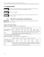
Replacement
7-21
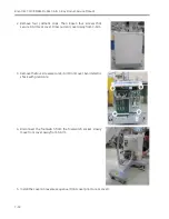
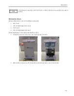
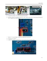
4.
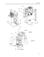
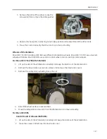
Remove all screws of the printer cabinet. Remove the printer cabinet.
5.
Remove the screws and disassemble two Workstation handles.
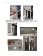
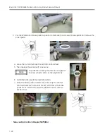
6.
Remove the screws on each side and remove the left and right upper side covers.
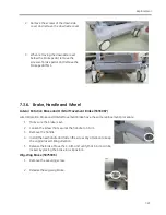
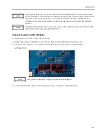
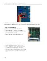
7.
Replace the cover and install them in reverse sequence.
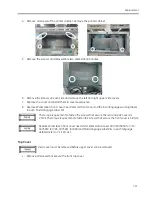
8.
Replace Workstation front cover need refer old front cover to affix local language warning labels
in each Multi-language Label Kit.
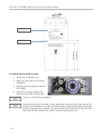
The torque requirement to fasten the screws that secure the rear and side covers is
2.5Nm.The torque requirement to fasten the screws that secure the front cover is 5.8Nm.
Replace Workstation front cover need order Workstation cover FRU (5075909 for 715,
5075910 for 785, 5075911 for 865) and Multi-language Label Kits in each language,
detailed refer to 7.1 FRU List.
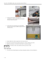
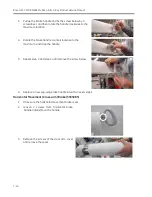
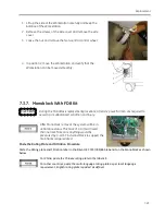
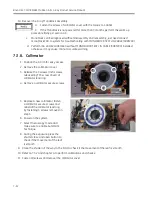
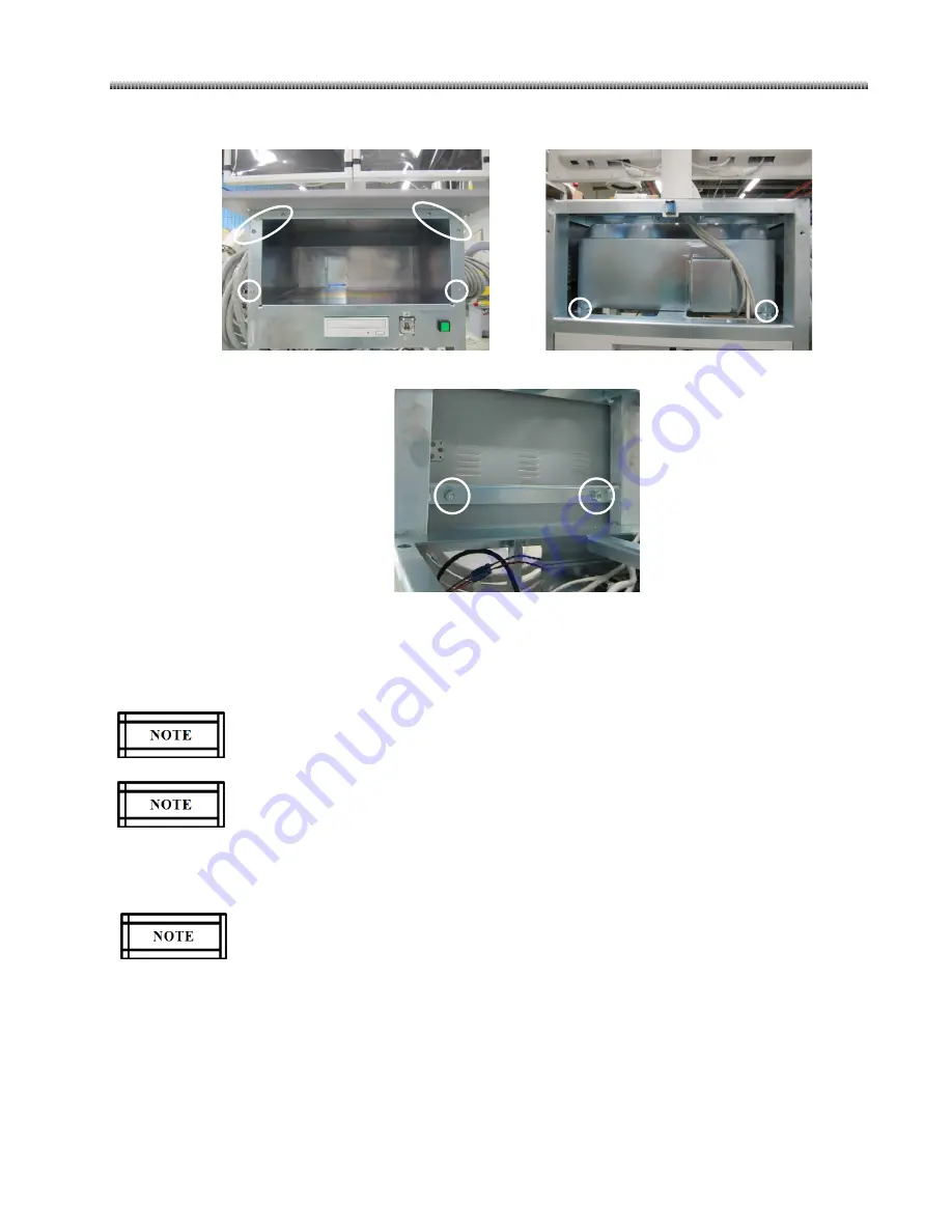
Top Cover
Rear cover must be removed before upper cover can be removed.
1.
Remove all screws that secure the front top cover.
Summary of Contents for Brivo OEC 715
Page 2: ......
Page 19: ...Chapter1 Introduction and Safety...
Page 41: ...Introduction and Safety 23 46 54 20 18 26...
Page 55: ...Chapter2 System Overview...
Page 137: ...Chapter3 Installation...
Page 212: ...Chapter4 Calibration...
Page 275: ...Brivo OEC 715 785 865 Mobile C Arm X Ray Product Service Manual 4 64...
Page 284: ...Chapter5 Software...
Page 326: ...Software 5 43 2 Click on install to continue 3 Click Next to continue...
Page 335: ...Chapter6 Troubleshooting...
Page 408: ...Chapter7 Replacement...
Page 418: ...Replacement 7 11 166...
Page 488: ...Chapter8 Periodic Maintenance...
Page 502: ...Periodic Maintenance 8 15...
Page 505: ...Chapter9 Technical Reference...
Page 521: ...Technical Reference 9 17 Vertical configuration 1 5m Vertical configuration 1m...
Page 526: ...11 Appendix System Schematics...


