– 21 –
Door Lock Assembly
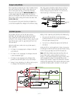
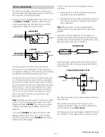
The door lock assembly consists of a lock motor
cam and switch assembly (switches #1, #2, #3, and
#4), lock hook, and mounting plate.
The lock motor is energized when the control is set
for
CLEAN
and
START
is selected. The RY1 relay
contacts will close and complete the circuit that
supplies the voltage to the lock motor.
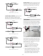
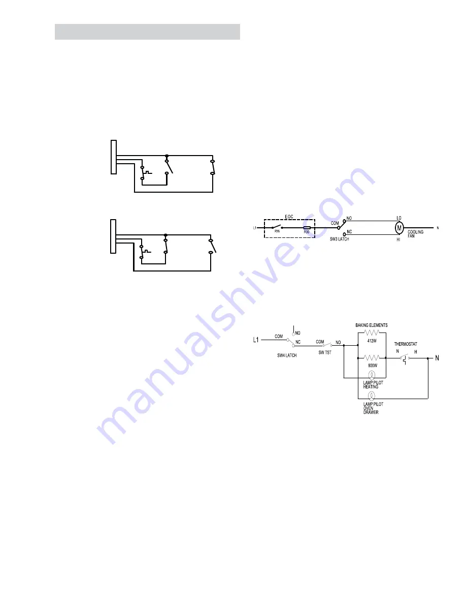
The lock switch circuit “tells” the control if the
lock motor is in the unlocked or locked position or
somewhere in between. There are two lock switches
mounted to and operated by the lock motor.
The lock switch circuit is from the control, through
one of the lock switches (switch #2 for unlocked or
switch #1 for locked), back to the control. If neither
switch is closed, and the oven temperature is below
600°F (315°C), control will energize the lock motor
circuit until the correct switch closes to complete
the circuit. (If circuit to the correct switch is open,
lock motor will run continuously with the oven
below 600°F [315°C].)
Note:
If initiating a clean cycle with the door switch
in the “C” to “NC” position (door open), the control
display will
fl
ash “
LOCKED
” and will sound a series
of beeps, followed by cancellation of the clean
selection.
• The word “
LOCKED
” will
fl
ash on and off in the
display while the lock motor is in motion. When
the door is locked, the word “
LOCKED
” will remain
illuminated in the display.
Note:
When the door is either being locked or
unlocked, both lock switches will be in the open
position.
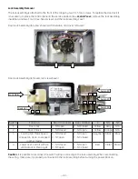
Switch #3 controls cooling fan motor speed. Hi
speed is used when the self-clean cycle is selected
and the door is locked and low speed for other oven
selections when the door is unlocked.
LOCKED
UNLOCKED
Switch #4 locks out the lower oven and all surface
units when the self-clean cycle is selected and the
door is locked.
COOLING FAN
LOCKOUTS IN CLEAN CYCLE
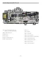
The door lock motor has an approximate resistance
value of 2K
Ω
.
The resistance of the door lock motor can be
checked on the ERC. Place the control panel in the
service position. (See
Control Panel
.)
With the door closed, test between TB660 (MDL) and
N on the ERC for the approximate resistance value.
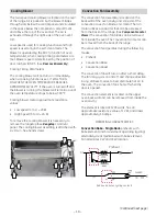
• CAM – The cam on the motor performs two
functions:
Positions the lock hook in the door to prevent
1.
opening during clean operation.
Operates the lock switches which tell the control
2.
if the door is unlocked or locked and ready for
clean operation.
(
Continued next page
)
DOOR LOCK
DOOR UNLOCK
SW2 LATCH
SW1 LATCH
CN2
3
4
5
DOOR LATCH OUTPUT PIN
DOOR LATCHED INPUT PIN
DOOR UNLATCHED INPUT PIN
THERMAL
SWITCH
DOOR LOCK
DOOR UNLOCK
SW2 LATCH
SW1 LATCH
CN2
3
4
5
DOOR LATCH OUTPUT PIN
DOOR LATCHED INPUT PIN
DOOR UNLATCHED INPUT PIN
THERMAL
SWITCH


