background image

Installation Instructions

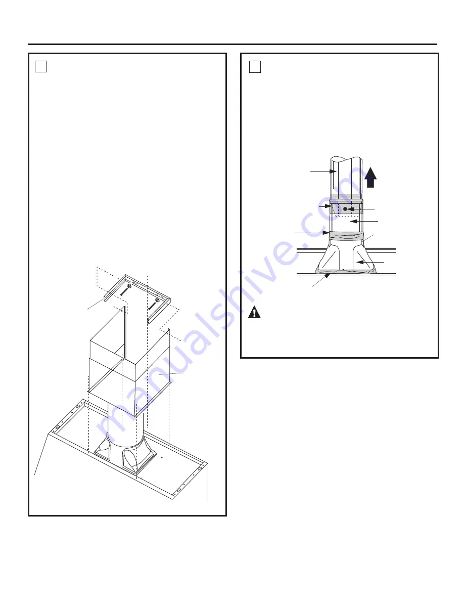
5  INSTALL CEILING BRACKET

The ceiling bracket must be installed when the duct
cover is used to span 24  or more height above the
hood. The bracket will hold the decorative duct cover
in place at the top.

Note:

 The ceiling bracket is not required when using

only the 12  section of the duct cover.
• Install the 2 small screws into the sides of the duct

bracket. Remove the screws. Pre-tapping the holes
will insure ease of final installation.

• Match center notch on the bracket to the centerline

on the wall and flush against the ceiling.

• Mark the 2 screw hole locations.
• Drill 1/8  pilot holes in marked bracket location.
• If pilot holes do not enter studs, enlarge the holes to

3/8  and install wall fastener anchors.

• Secure the bracket to the rear wall with wood screws

and washers. Use wall anchors if needed.

6  CONNECT DUCTWORK

• Push duct over the end of the transition until it

reaches the stop tabs.

• Install ductwork, making connections in direction of

airflow as illustrated.

• Secure joints in ductwork with sheetmetal screws.
• Wrap all duct joints with duct tape for an airtight

seal.

• Use duct tape to seal the flange connection.

CAUTION:

 Do not use sheet metal

screws at the transition to ductwork connection.
Doing so will prevent proper damper operations. 
Seal connection with tape only.

Screw

Duct Tape
Over Seam 
and Screw

Air Flow

Duct Tape

Over Flange

Duct

Stops

Note: 

Bracket has 2 sets of holes. Use larger holes for wall

fasteners or wood screws with washers. Use smaller holes for
wood screws with washers.

See Step 9

to Install

Duct Cover

Install

Ceiling Bracket

When Duct

Cover is

Used to Span

24" or More

Ductwork

Transition

Duct Tape

Only for Proper
Operation
of Damper

House Ductwork

16

Summary of Contents for Cafe CV936MSS

Page 1: ...s 6 Stainless Steel Surfaces 5 Installation Instructions 7 18 Troubleshooting Tips 19 Consumer Support Consumer Support 24 Owner Registration 21 22 Warranty 23 Write the model and serial numbers here...

Page 2: ...o properly exhaust air be sure to duct air outside Do not vent exhaust air into spaces within walls or ceilings or into attics crawl spaces or garages WARNING TO REDUCE THE RISK OF INJURY TO PERSONS I...

Page 3: ...TO PERSONS OBSERVE THE FOLLOWING A Installation work and electrical wiring must be done by qualified person s in accordance with all applicable codes and standards including fire rated construction B...

Page 4: ...humid It also reduces cooking odors and soiling moisture that create a frequent need for cleaning NOTE When the fan is operating on the LO setting it will be very quiet Always make sure that the fan i...

Page 5: ...se shake and let them dry before replacing To remove Grasp the filter handle and pull it up forward and out To replace Hold the filter at the bottom with the handle Place the top end of the filter aga...

Page 6: ...amp cloth To remove Turn the glass cover counterclockwise until the glass cover clears the socket Using gloves or a dry cloth remove the bulb by pulling it straight out To replace Use a new 12 volt 20...

Page 7: ...ctrical skills Completion time 1 to 3 hours Proper installation is the responsibility of the installer Product failure due to improper installation is not covered under the Warranty CAUTION Due to the...

Page 8: ...ll They may be installed beneath a soffit or cabinet Install these hoods 24 Min to 36 Max above the cooking surface 2 Piece Duct Cover With Ceiling Bracket 2 Phillips Head Decorative Screws SOFFIT SOF...

Page 9: ...l service DUCT FITTINGS Follow these guidelines for proper duct sizing in the ducting charts POWER SUPPLY IMPORTANT Please read carefully WARNING FOR PERSONAL SAFETY THIS APPLIANCE MUST BE PROPERLY GR...

Page 10: ...as possible Do NOT use flexible plastic ducting Total Duct Run Any home ventilation system such as a ventilation hood may interrupt the proper flow of combustion air and exhaust required by fireplace...

Page 11: ...12 rectangular duct length to suit installation Wire Cutter Stripper Ladder Allen Wrench REMOVE THE PACKAGING Lift the hood out of the box Remove shipping screws holding the wood mounting piece to the...

Page 12: ...ceiling bracket must be installed to secure the cover at the top To avoid unsightly gaps plan the hood installation height for duct cover use The cover will fit a 12 min height from the top of the TH...

Page 13: ...per cabinet Follow the same procedure for ceiling ducting to cut the 7 1 2 dia hole through the top of the cabinet or soffit See Step 4 page 15 for details to cut opening for duct transition 13 DETERM...

Page 14: ...ood should engage the protruding mounting screws Allow the hood to slide down into position Pull house wiring through knockout at the rear or the top of the hood Check to be sure the hood is level and...

Page 15: ...tuds Dim A at locations shown in the above chart Allow minimum opening Dim B to accommodate the duct transition in the soffit Cut a 10 3 4 x 8 7 16 hole through bottom of soffit or cabinet for duct tr...

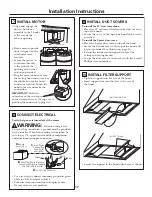
Page 16: ...the rear wall with wood screws and washers Use wall anchors if needed 6 CONNECT DUCTWORK Push duct over the end of the transition until it reaches the stop tabs Install ductwork making connections in...

Page 17: ...lots Secure the support to the hood with screws as shown 10 INSTALL FILTER SUPPORT Tip filter support into the rear of the hood Insert support tabs into the slots at the rear of the hood Plug the moto...

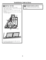
Page 18: ...l front panel Tap the filter against one side to align with outside opening Pull the filter down into the lower slots at the bottom of the filter support To remove the filters grasp the handle push th...

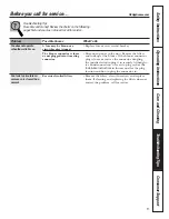
Page 19: ...e blower connector is loose Disconnect power to the unit Remove the filters or not plugged into its mating and look up at the blower If the blower connector connector plug is loose or you see the conn...

Page 20: ...20 Consumer Support Troubleshooting Tips Operating Instructions Safety Instructions Care and Cleaning Notes...

Page 21: ...21 OWNERSHIP REGISTRATION P O BOX 1780 MISSISSAUGA ONTARIO L4Y 4G1 FOR CANADIAN CONSUMERS ONLY Please place in envelope and mail to Veuillez mettre dans une enveloppe et envoyez...

Page 22: ...22...

Page 23: ...you may be required to bring the product to an Authorized GE Service Location for service In Alaska the warranty excludes the cost of shipping or service calls to your home Some states do not allow th...

Page 24: ...ts For details of GE s Universal Design applications including kitchen design ideas for people with disabilities check out our Website today For the hearing impaired please call 800 TDD GEAC 800 833 4...

Page 25: ...Surfaces en acier inoxydable 5 Directives d installation 7 18 D pannage 19 Service la client le Garantie 23 Inscription du propri taire 21 22 Service la client le 24 Inscrivez ci dessous les num ros...

Page 26: ...er une vacuation ad quate de l air assurez vous d acheminer les conduits vers l ext rieur N vacuez pas l air dans les espaces entre les murs dans le plafond ou le grenier ni dans un vide sanitaire ou...

Page 27: ...ESSURES OBSERVEZ LES CONSIGNES QUI SUIVENT A Les travaux d installation et de c blage lectrique doivent tre effectu s par une personne qualifi e conform ment tous les codes et normes applicables y com...

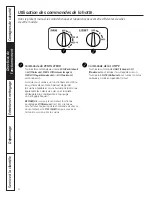
Page 28: ...Cela diminue galement les odeurs de cuisson et la salet attribuable la condensation et qui exige un nettoyage fr quent REMARQUE Lorsque le ventilateur fonctionne au r glage LO Minimum il est tr s sile...

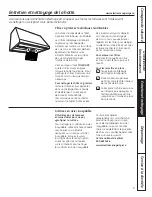
Page 29: ...les filtres avant de les remettre en place Pour enlever les filtres Saisissez la languette du filtre et tirez la vers le haut puis vers l avant Pour les remettre en place Tenez la partie inf rieure d...

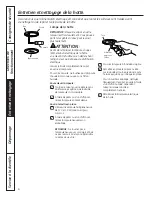
Page 30: ...n chiffon humide Pour enlever l ampoule Tournez le capot en verre dans le sens antihoraire jusqu ce que la douille de l ampoule soit accessible l aide de gants ou d un chiffon sec retirez l ampoule en...

Page 31: ...quate n est pas couverte par la garantie Directives Hottes de cuisine d installation ATTENTION Compte tenu du poids et de la dimension de cette hotte et pour r duire les risques de blessures et de dom...

Page 32: ...vous la page 12 ACCESSOIRES FACULTATIFS Couvre conduit Il existe un couvre conduit d coratif pour les installations lorsque la hauteur du plafond varie entre 2 4 m 8 pi et 3 0 m 10 pi Ce couvre condui...

Page 33: ...mur Vous pourrez ainsi d terminer l emplacement pr cis pour le conduit et le c blage lectrique COUVRE CONDUIT D CORATIF Ilexisteuncouvre conduitd coratifconvenant cemod le Cecouvre conduitdissimulelec...

Page 34: ...tangulaire de 8 2 cm 3 1 4 po x 30 4 cm 12 po un conduit circulaire de 17 8 cm 7 po 0 3 m 1 pi Coude de transition de 90 circulaire de 17 8 cm 7 po conduit rectangulaire de 8 2 cm 3 1 4 po x 30 4 cm 1...

Page 35: ...S NON FOURNIS Crayon et ruban mesurer Pince Pince coupante d nuder Cisailles t les Cl Allen Niveau bulle Ruban adh sif pour conduit Lunettes de s curit Escabeau Scie sauteuse ou scie guichet Tournevis...

Page 36: ...e 60 9 cm 24 po et 86 3 cm 34 po entre le dessus de la hotte et le plafond VOUS NE POUVEZ PAS UTILISER LE COUVRE D TECTEUR SI LA DISTANCE ENTRE LE DESSUS DE LA HOTTE ET LE PLAFOND VARIE ENTRE 30 4 CM...

Page 37: ...t droit Pour acheminer le c blage par le plafond ou la retomb e de plafond Percez un trou d environ 2 5 cm 1 po de diam tre 14 3 cm 5 7 8 po du mur 28 2 cm 11 1 8 po droite de la ligne centrale dans...

Page 38: ...s fournies Utilisez du ruban adh sif pour conduit pour sceller le raccord 2 Conduit de transition Enlevez le ruban gomm sur le registre Dessus de la hotte INSTALLATION DE LA HOTTE AU MUR Soulevez la h...

Page 39: ...n suppl mentaire et pour r duire au minimum les vibrations pendant le fonctionnement de l appareil nous vous recommandons fortement de fixer galement la hotte au mur l aide de chevilles d ancrage pour...

Page 40: ...es de trous Utilisez les gros trous pour les chevilles d ancrage ou les vis bois avec rondelles Utilisez les petits trous pour les vis bois avec rondelles 5 Installez le support de plafond lorsque le...

Page 41: ...le IMPORTANT Tenez le connecteur de sorte que les deux bornes carr es dans les coins soient vers le haut du connecteur pour le brancher 7 INSTALLATION DU SUPPORT DE FILTRE Inclinez le support de filt...

Page 42: ...t vis vis de l ouverture ext rieure Poussez sur le filtre afin qu il soit ins r dans les fentes inf rieures au bas du support de filtre Pour enlever les filtres saisissez la languette du filtre et tir...

Page 43: ...ur du ventilateur Coupez l alimentation lectrique de la hotte est l che ou d branch Enlevez les filtres et inspectez le ventilateur Si le connecteur du ventilateur est l che ou d branch c est que l in...

Page 44: ...20 Notes Consignes de s curit Directives de fonctionnement D pannage Service la client le Entretien et nettoyage...

Page 45: ...21 OWNERSHIP REGISTRATION P O BOX 1780 MISSISSAUGA ONTARIO L4Y 4G1 FOR CANADIAN CONSUMERS ONLY Please place in envelope and mail to Veuillez mettre dans une enveloppe et envoyez...

Page 46: ...22...

Page 47: ...illez fournir le num ro de s rie et le num ro de mod le lorsque vous appelez pour obtenir le service Agrafez votre facture ici La preuve d achat originale sera n cessaire pour b n ficier des services...

Page 48: ...ent recevoir pi ces et accessoires directement la maison cartes VISA MasterCard et Discover accept es Les directives stipul es dans le pr sent manuel peuvent tre effectu es par n importe quel utilisat...

Reviews: