Summary of Contents for CAL16A

Page 1: ...090A INSTRUCTIONS S U P E f t l E O t t G E f 9 0 9 NETWORK RELAYS Types C ALI6 A CAN13 A W BI won POWER SYSTEMS MANAGEMENT DEPARTMENT A Si GENERAL ELECTRIC PHILADELPHIA PA Courtesy of NationalSwitchgear com ...

Page 2: ...Courtesy of NationalSwitchgear com ...

Page 3: ... the same as that ordinarily used with the Type CAN11A relay t e 340 ohms when 6054972 G8 is used as the phase shifting trans former and when the 900 ohm resistor is used in the phase circuit for 1 5 volt reclosure Therefore the tripping characteristic is the same except that the setting is 0 1 instead of 0 2 of the relay rating RECEIVING HANDLING AND STORAGE CO The relays when not included as a p...

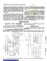
Page 4: ...place the relay unit the reverse order Is followed A separate testing plug can be Inserted In place of the connecting plug to test the relav In place the panel either from Its own source of current and voltage or from other sources Or the relay unit can be drawn out and replaced by another which has been tested Ln the laboratory in the case with a latch on INSTALLATION LOCATION AND MOUNTING dimens...

Page 5: ... i r i rX 11 H X H X vn 4 5 6 I I 40 I w T3 T2 T1 CO I L J CAN13A CURRENT CO ILS b u i in n n 1 r ir 1 15 161 T 114 r fY I PHASE SHIFTING I TRANSFORMER T2 FT31 6054972 G 8 11 Y Y n I x lPw 8 19 17 18 6 J J HJ J i n n n j i rv I CAN13A POTENTIAL COILS CAL16A POTENTIAL COILS 125V X CIRCUIT BREAKER TO NETWORK Fig 3 External Connections For Types CAL 16 A And CAM 13A Relays 5 Courtesy of NationalSwitc...

Page 6: ...X o 9 8 0 5 0 0 6 3 o i V u 16 1 1 CURRENT CIRCUITS POTENTIAL CIRCUITS RECLOSIRG 2 t J N r j T 900 900 900 A 19 605 8972 0 MU SHIFTING TRAN f 0 RM CR T T r 17 Q H N H x X 0 H X 6 18 16 1 POTENTIAL CIRCUITS CURRENT CI RCU ITS Schematic Diagram Of Teat Connections For Relay Type CAN 13A Fig 4 6 Courtesy of NationalSwitchgear com ...

Page 7: ...ase current is equal to 1 5 times the desired three phase trip setting For example If it is desired to trip at 0 005 amperes balanced three phase current the ammeter A should read 0 0075 amperes because of the single phase current The trip calibration can be adjusted above or below the factory setting or the factory setting can be restored by adjusting the main control spring adjusting shaft see p...

Page 8: ...o 0 5 volt leading the potential voltage studs 5 6 by 90 degrees Adjustments can be made as described in GEI 13580 The reclose calibration of the relay can be changed by adjusting the mechanical restraint ele ment Turning the cap of the restraint clockwise increases the restraint and therefore the reclose calibration Holding Coils Both holding coils of the Type CAN13A relay are rated 2 amperes The...

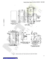
Page 9: ... OUTLINE a u IJ 5 to 16 27 2 27 1 UJ 2 j 32 32 32 JO J i PANEL L cc 4 DRILL 6 HOLES o O mjco 18 STUD Z NE 2 4DRILL VO HCcEt r j CM fO fO to K UI If o _J O a s 1 5 3 x CM 3 2 X c 2 1 A 5 c 10 rO K 2 tL If i N 1 y H VIEW SHOWING ASSEMBLY OF HARDWARE FOR SURFACE MTG ON STEEL PANELS It 3 tic 3_L 2 3 o MJFLUSH PANEL DRILLING MOUNTING F 4 PANEL DRILLING FOR SURFAi t MOUNTING FRONT VIEW FIg 6 Outline And...

Page 10: ...ONT VIEW r IKD 32 c p MTG 1 y SCREW a u _ OUTLINE i hi I Q a8 r LCio3o arj i YDFUL q 6 HOLES J T O PANEL He 3 I K JO fO NjCO I8 STUD D 8 m OC T T a foh ffi mco in 3 I 4 4 X o fcui Ui j 0 lo IJJ j J R ro c 3 8 m CM tr L VIEW SHOWING ASSEMBLY OF HARDWARE FOR SURFACE MTG ON STEEL PANELS F O PANEL DRILLING FOR SURFACE MOUNTING FRONT VIEW PANEL DRILLING FOR SEMI FLUSH MOUNTING FRONT VIEW Outline And Pa...

Reviews: