MA-037 - CB Watch 3 Operating Manual
v7.0 - May 2020
Page 70 of 118
CONTROL CIRCUIT MONITORING
General description
This section covers monitoring the various CB command circuits and ensuring that any open
or close command, sent manually or by a protection relay, can be executed.
DC Supply
DC supply level
While a circuit breaker will fail to receive any command if there is no DC voltage present or
if it is extremely low, the time taken for the operation may be affected by the presence of a
lower than nominal DC voltage (as has been explained earlier in this manual). This can occur
when the DC power is supplied by substation batteries not in optimal shape and when
several operations are taking place at the same time.
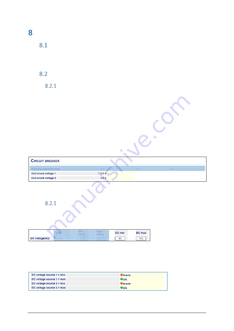
With the appropriate sensor installed, the CBW3 can continually monitor DC voltage source
1 (and DC voltage source 2 if present) that supply the coil circuit voltage. The values are
displayed in the HMI:
HMI: Measurement / Sensors
Figure 107
–
Continuous display of DC voltage for source 1 and 2
DC supply alarm
An alarm can be set for each of the DC voltage sources with both a minimum and maximum
threshold.
HMI: Settings / Analogue channels
Figure 108
–
DC voltage alarm thresholds
Any alarm is displayed in the HMI under the
“Alarms related to continuous measurements”
section.
HMI: Measurements / Alarms
Figure 109
–
DC voltage alarms


