


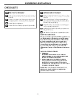


4
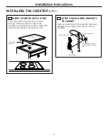
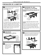
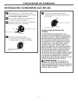
CUTOUT DIMENSIONS
Of THE COUNTERTOP
To insure accuracy, it is best to make a template
when cutting the opening in the counter.
JXTR32X CUTOUT fILLER TRIM KIT:
A filler trim kit is available for use if your countertop
cutout is larger than the dimensions shown, up to
29-13/16" x 20-7/16". O rder JXTR32X to reduce the
cutout opening for installation of this cooktop. This
kit may be ordered from your GE Dealer.
4
Installation Instructions
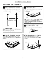
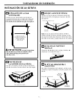
1
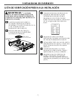
The following MINIMUM clearance dimensions
must be maintained.
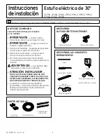
PREPARINg THE OPENINg
2
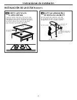
OVERALL COOKTOP DIMENSIONS
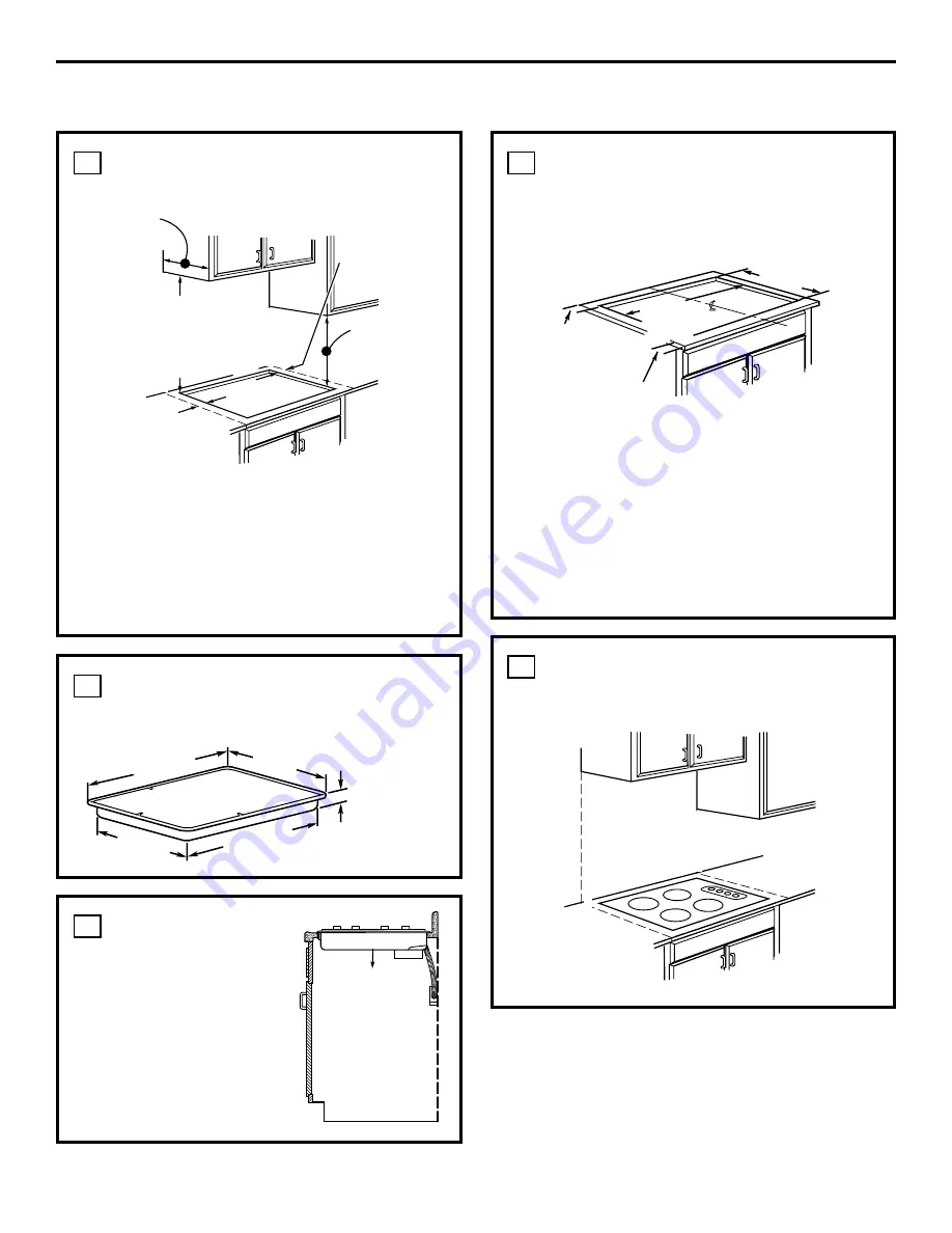
3
Five inches (5")
minimum vertical
clearance between
the cooktop bottom
and any combustible
surfaces.
5
Make sure the wall coverings, countertop and
cabinets around the cooktop can withstand
heat (up to 200°F) generated by cooktop.
13" MAX. Depth of uprotected
overhead cabinets
30" MIN.
Clearance from
countertop to
unprotected
overhead
surface
2" MIN. Clearance
from cutout to side
wall on the left of
the unit
15" MIN. Height
from countertop to
nearest cabinet on
either side of unit
1-1/2" MIN.
Clearance from
cutout to side wall
on the right of the
unit
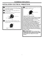
28"
Cooktop
29-3/4"
(29-7/8" SS)
19-1/4"
3-1/4" Front
4-5/8" Rear
at the conduit
location
6-1/4" Rear
on Model PP945
& PP950
5" Min.
Vertical Clearance
Wall covering,
cabinets and
countertop must
withstand heat up
to 200°F.
2-1/2" Min.
from front edge
of cutout and
front edge of
countertop
19-5/8" width of cut
28-1/2"
length of
cut
1-3/4" Min. Between
cutout and the wall
behind the cooktop
If a 30" clearance between the cooking surface
and overhead combustible materials or metal
cabinets cannot be maintained, a minimum
clearance of 24" is required and the underside
of the cabinets above the cooktop must be
protected with not less than 1/4" insulating
millboard covered with sheet metal not less than
0.0122" thick.
21-3/8" (21-1/2" SS)


