


5
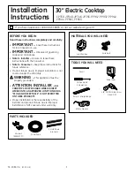
Installation Instructions
1
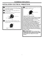
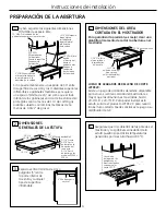
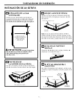
INSTALLINg THE JUNCTION BOX
Install an approved junction box where it will be
easily reached through the front of the cabinet
where the cooktop will be located. The cooktop
conduit is 3 feet long.
IMPORTANT:
The junction box must be
located where it will allow considerable slack in
the conduit for serviceability.
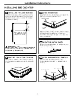
INSTALLINg THE COOKTOP
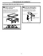
3
ATTACH fOAM TAPE
Apply the foam tape around the outer edge of the
glass. Do not overlap the foam tape.
Note: On CP350S, PP912S, PP932S, PP942S, PP944S,
PP945S & PP950S models, apply the foam tape
around the outer edge of the glass on the sides and
rear of the unit only.
4
LOCATE MOUNTINg PARTS
Remove the hold down brackets and screws from
the literature package.
5
ATTACH BRACKETS TO COOKTOP
Screw the hold down bracket to the side
of the cooktop unit. Repeat for opposite side of
cooktop.
Hold Down
Bracket
Pre-Drilled Hole
Bottom of Cooktop
Cooktop Glass
Foam Tape
Install junction box so that
it can be reached through
the front of the cabinet.
16”
Min.
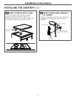
2
PROTECT SURfACE Of COOKTOP
Place a towel or tablecloth onto the countertop.
Lay the cooktop upside down onto the protected
surface.
Bottom of Cooktop
Cloth under Cooktop
Bottom of Cooktop
Foam Tape
Cooktop
Glass
Mounting Screw


