background image

8

Installation Instructions
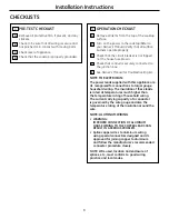
1


PRE-TEST CHECKLIST

  Remove all protective film, if present, and any 

stickers.

  Check to be sure that all wiring is secure and 

not pinched or in contact with moving parts.

  Check level of appliance.

  Check that the cooktop is properly grounded.

CHECKLISTS

2


OPERATION CHECKLIST

  Remove all items from the top of the cooktop 

surface.

  Turn on the power to the cooktop.(Refer to 

your Owner’s Manual.) Verify that all surface 

burners operate properly.

  Check that the circuit breaker is not tripped 

nor the house fuse blown.

  Check that conduit is securely connected to 

the junction box.

  See Owner’s Manual for troubleshooting list.

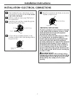
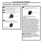
NOTE TO ELECTRICIAN:

The power leads supplied with this appliance are 

UL recognized for connections to larger gauge 

household wiring. The insulation of these leads 

is rated at temperatures much higher than 

the temperature rating of household wiring. 

The current carrying capacity of a conductor 

is governed by the wire gauge and also the 

temperature rating of the insulation around the 

wire.

NOTE: ALUMINUM WIRINg

•  WARNINg:

IMPROPER CONNECTION Of ALUMINUM 

HOUSE WIRINg TO THE COPPER LEADS CAN 

RESULT IN A SERIOUS PROBLEM.

•  Splice copper wires to aluminum wiring 

using special connectors designed and UL 

approved for joining copper to aluminum 

and follow the manufacturer’s recommended 

connector procedure closely.

NOTE: Wire used, location and enclosure of 

splices, etc., must conform to good wiring 

practice and local codes.

Summary of Contents for CP350

Page 1: ...er the Warranty WARNING This appliance must be properly grounded ATTENTION INSTALLER ALL COOKTOPS MUST BE HARD WIRED DIRECT WIRED INTO AN APPROVED JUNCTION BOX A PLUG AND RECEPTACLE IS NOT PERMITTED ON THESE PRODUCTS Proper installation is the responsibility of the installer and product failure due to improper installation is NOT covered under warranty Wire Nuts Junction Box Saber Saw Pencil Safet...

Page 2: ... fatal shock Know where your main disconnect switch is located If you do not know have your electrician show you IMPORTANT SAFETY INSTRUCTIONS Electrical Requirements This appliance must be supplied with the proper voltage and frequency and connected to an individual properly grounded branch circuit protected by a circuit breaker or a time delay fuse as noted on name plate We recommend you have th...

Page 3: ... literature pack and read them carefully before you begin Be sure to place all literature Owner s Manual Installations etc in a safe place for future reference D Make sure you have all the tools and materials you need before starting the installation of the cooktop E Your home must provide the adequate electrical service needed to safely and properly use your cooktop Refer to section on electrical...

Page 4: ...overhead cabinets 30 MIN Clearance from countertop to unprotected overhead surface 2 MIN Clearance from cutout to side wall on the left of the unit 15 MIN Height from countertop to nearest cabinet on either side of unit 1 1 2 MIN Clearance from cutout to side wall on the right of the unit 28 Cooktop 29 3 4 29 7 8 SS 19 1 4 3 1 4 Front 4 5 8 Rear at the conduit location 6 1 4 Rear on Model PP945 PP...

Page 5: ... PP950S models apply the foam tape around the outer edge of the glass on the sides and rear of the unit only 4 Locate Mounting Parts Remove the hold down brackets and screws from the literature package 5 Attach Brackets to Cooktop Screw the hold down bracket to the side of the cooktop unit Repeat for opposite side of cooktop Hold Down Bracket Pre Drilled Hole Bottom of Cooktop Cooktop Glass Foam T...

Page 6: ...l to the cooktop Make final check that all required clearances are met Installing the Cooktop CONT 7 Attach Hold Down Brackets to Cabinet Open the cabinet door and screw the hold down brackets to the cabinet sides with the screws provided Hold Down Bracket Cooktop Mounting Screw Burner Box Sides Use suitable fasteners for anchorage in cabinet sides Cabinet Side ...

Page 7: ...Electrical Code will not permit grounding through neutral If used in new construction after January 1 1996 or in a mobile home recreational vehicle or if local codes do not permit grounding through the neutral white lead attach the appliance grounding lead green or copper to the residence grounding conductor green or bare copper in accordance with local codes When connecting to a 3 conductor branc...

Page 8: ...or troubleshooting list NOTE TO ELECTRICIAN The power leads supplied with this appliance are UL recognized for connections to larger gauge household wiring The insulation of these leads is rated at temperatures much higher than the temperature rating of household wiring The current carrying capacity of a conductor is governed by the wire gauge and also the temperature rating of the insulation arou...

Page 9: ...por la Garantía ADVERTENCIA Este aparato debe descargarse a tierra correctamente ATENCIÓN INSTALADOR TODAS LAS ESTUFAS DEBEN CONTAR CON CABLEADO CABLEADO DIRECTO A UNA CAJA DE EMPALMES APROBADA ESTOS PRODUCTOS NO ACEPTAN ENCHUFES Y RECEPTÁCULOS La instalación correcta es responsabilidad del instalador y el mal funcionamiento del producto debido a una instalación inadecuada NO está cubierto bajo la...

Page 10: ... localiza el interruptor principal de desconexión Si no lo sabe pídale a su electricista que le muestre la ubicación INSTRUCCIONES DE SEGURIDAD IMPORTANTES REQUISITOS ELÉCTRICOS Este aparato debe contar con el voltaje y frecuencia adecuados y deberá conectarse a un circuito derivado individual debidamente descargado a tierra protegido por un cortacircuitos o un fusible temporizado como lo indica l...

Page 11: ...rial impreso y léalas cuidadosamente antes de comenzar Asegúrese de colocar todo el material impreso Manual de propietario Instalaciones etc en un lugar seguro para referencia futura D Asegúrese de contar con todas las herramientas y materiales que necesita antes de comenzar la instalación de la estufa E Su hogar debe contar con el servicio eléctrico adecuado para el uso seguro y correcto de su es...

Page 12: ...en seguirse las siguientes dimensiones MÍNIMAS de espacio libre 2 DIMENSIONES GENERALES DE LA ESTUFA 3 Espacio vertical mínimo de cinco pulgadas 5 entre la parte inferior de la estufa y cualquier tipo de superficie inflamable 13 MÁX Profundidad de los gabinetes superiores sin protección 30 MÍN Espacio desde el mostrador hasta la superficie superior sin protección 2 MÍN Espacio desde el área cortad...

Page 13: ...drio No aplique un exceso de cinta de espuma Nota En los modelos CP350S PP912S PP932S PP942S PP944S PP945S y PP950S aplique la cinta de espuma únicamente alrededor del borde exterior del vidrio en los lados y parte posterior de la unidad 4 LocaLICE LAS PARTES DE MONTAJE Saque las abrazaderas de montaje y tornillos del empaque con material impreso 5 SUJETE LAS ABRAZADERAS A LA ESTUFA Atornille la a...

Page 14: ...os Tornillo de montaje Lados de la caja de hornillas Use sujetadores adecuados para fijación a los lados del gabinete Lado del gabinete 6 InsertE LA ESTUFA EN EL ÁREA CORTADA Inserte la estufa centrada en el área cortada Asegúrese de que el borde frontal del mostrador esté paralelo con respecto a la estufa Asegúrese de verificar al final que todos los espacios especificados hayan sido respetados A...

Page 15: ...a tierra a través de cables neutrales Si se usa en una construcción nueva después del 1 de enero de 1996 o bien en una casa rodante vehículo recreativo o bien si los códigos locales no permiten la descarga a tierra a través de cables blancos neutrales sujete el cable de descarga a tierra del aparato verde o cobre al conductor de descarga a tierra de la residencia verde o cobre de acuerdo con los c...

Page 16: ...el Manual del propietario para ver la lista de resolución de problemas NOTA PARA EL ELECTRICISTA Los cables de corriente incluidos con este aparato cuentan con la aprobación de UL para conexiones a cableado doméstico de mayor calibre El aislante de estos cables se califica a temperaturas más elevadas que las del cableado doméstico La capacidad de carga actual de un conductor depende del calibre de...

Reviews: